
Page 676 - Fundamentals of Water Treatment Unit Processes : Physical, Chemical, and Biological
P. 676
Disinfection 631
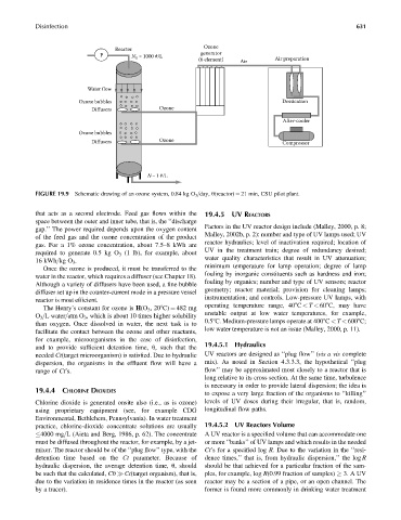
Ozone
Reactor
generator
P N = 1000 #/L (6 element) Air Air preparation
0
Water flow
Ozone bubbles Dessication
Diffusers Ozone
After-cooler
Ozone bubbles
Diffusers Ozone Compressor
N= 1 #/L
FIGURE 19.9 Schematic drawing of an ozone system, 0.84 kg O 3 =day, u(reactor) ¼ 21 min, CSU pilot plant.
that acts as a second electrode. Feed gas flows within the 19.4.5 UV REACTORS
space between the outer and inner tube, that is, the ‘‘discharge
Factors in the UV reactor design include (Malley, 2000, p. 8;
gap.’’ The power required depends upon the oxygen content
Malley, 2002b, p. 2): number and type of UV lamps used; UV
of the feed gas and the ozone concentration of the product
reactor hydraulics; level of inactivation required; location of
gas. For a 1% ozone concentration, about 7.5–8 kWh are
UV in the treatment train; degree of redundancy desired;
required to generate 0.5 kg O 3 (1 lb), for example, about
water quality characteristics that result in UV attenuation;
16 kWh=kg O 3 .
minimum temperature for lamp operation; degree of lamp
Once the ozone is produced, it must be transferred to the
fouling by inorganic constituents such as hardness and iron;
water in the reactor, which requires a diffuser (see Chapter 18).
fouling by organics; number and type of UV sensors; reactor
Although a variety of diffusers have been used, a fine bubble
geometry; reactor material; provision for cleaning lamps;
diffuser set up in the counter-current mode in a pressure vessel
instrumentation; and controls. Low-pressure UV lamps, with
reactor is most efficient.
operating temperature range, 408C < T < 608C, may have
The Henry’s constant for ozone is H(O 3 ,208C) ¼ 482 mg
unstable output at low water temperatures, for example,
O 3 =L water=atm O 3 , which is about 10 times higher solubility
0.58C. Medium-pressure lamps operate at 4008C < T < 6008C;
than oxygen. Once dissolved in water, the next task is to
low water temperature is not an issue (Malley, 2000, p. 11).
facilitate the contact between the ozone and other reactants,
for example, microorganisms in the case of disinfection,
and to provide sufficient detention time, u, such that the 19.4.5.1 Hydraulics
needed Ct(target microorganism) is satisfied. Due to hydraulic UV reactors are designed as ‘‘plug flow’’ (vis a vis complete
dispersion, the organisms in the effluent flow will have a mix). As noted in Section 4.3.3.3, the hypothetical ‘‘plug
range of Ct’s. flow’’ may be approximated most closely to a reactor that is
long relative to its cross section. At the same time, turbulence
is necessary in order to provide lateral dispersion; the idea is
19.4.4 CHLORINE DIOXIDES to expose a very large fraction of the organisms to ‘‘killing’’
Chlorine dioxide is generated onsite also (i.e., as is ozone) levels of UV doses during their irregular, that is, random,
using proprietary equipment (see, for example CDG longitudinal flow paths.
Environmental, Bethlehem, Pennsylvania). In water treatment
practice, chlorine-dioxide concentrate solutions are usually 19.4.5.2 UV Reactors Volume
4000 mg=L (Aieta and Berg, 1986, p. 62). The concentrate A UV reactor is a specified volume that can accommodate one
must be diffused throughout the reactor, for example, by a jet- or more ‘‘banks’’ of UV lamps and which results in the needed
mixer. The reactor should be of the ‘‘plug flow’’ type, with the Ct’s for a specified log R. Due to the variation in the ‘‘resi-
detention time based on the Ct parameter. Because of dence times,’’ that is, from hydraulic dispersion,’’ the log R
hydraulic dispersion, the average detention time, u, should should be that achieved for a particular fraction of the sam-
be such that the calculated, Cu Ct(target organism), that is, ples, for example, log R(0.99 fraction of samples) 3. A UV
due to the variation in residence times in the reactor (as seen reactor may be a section of a pipe, or an open channel. The
by a tracer). former is found more commonly in drinking water treatment