
Page 675 - Fundamentals of Water Treatment Unit Processes : Physical, Chemical, and Biological
P. 675
630 Fundamentals of Water Treatment Unit Processes: Physical, Chemical, and Biological
(150 lb=mgal), which is very high, then the chlorination feed
capacity must be 680 kg Cl 2 =day (1500 lb=day), that is,
3
3
J(Cl 2 ) ¼ Q C(Cl 2 ) ¼ 0.44 m =s 0.018 kg Cl 2 =m ¼ 0.00792
kg Cl 2 =s ¼ 684 kg Cl 2 =day. To provide for the logistics, that
is, storage and delivery frequency, this is about 20,520 kg
Cl 2 =month, or 22 ton-cylinders=month. At 208C and a vacuum
backpressure, J(Cl 2 )max 230 kg Cl 2 =day (500 lb=day) from
a ton-cylinder; thus about three cylinders should be online in
parallel (connected to a manifold).
19.4.1.2 Reactor Design
The chlorine reactor should provide for turbulent mixing at
the diffuser, followed by plug flow to achieve the desired
detention time. Long narrow channels should be used to
minimize the extent of short-circuiting; perfect plug flow, is
of course, not achievable. Tracer tests may be conducted to
confirm dispersion curves for different flows, or computa-
tional fluid mechanics (CFD) modeling may be conducted to
examine alternative designs. In most cases, retrofits are
installed, for example, partitions in rectangular or circular
basins to give a ‘‘serpentine’’ flow pattern. A reactor with
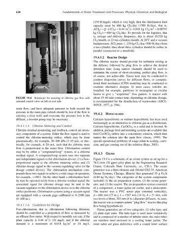
FIGURE 19.8 Rotometer for metering of chlorine gas flow with about 15–60 min contact time, depending on chlorine dosage,
actuated control valve on left on exit side. is recommended for the disinfection of wastewaters (ASCE-
WPCF, 1977, p. 394).
main flow, and have adequate pressure to both exceed the
pressure in the main pipe (which should be low if the flow is
19.4.2 HYPOCHLORITE
entering a clear well) and overcome the pressure loss in the
diffuser, a booster pump may be necessary. Calcium hypochlorite or sodium hypochlorite has been used
increasingly as an alternative to chlorine gas as a disinfectant.
19.4.1.1.5 Chlorine Metering and Control Calcium hypochlorite, Ca(OCl) 2 , is a solid and is favored. In
Chlorine residual monitoring and feedback control are neces- addition, package feed and metering systems are available that
sary components of a system. Either the flow signal is used to feed Ca(OCl) 2 tablets into a concentrate solution, which then
control the chlorine-metering orifice, which may be done meters the solution into the main flow (Anon., 1999). The
pneumatically, for example, 20–100 kPa (3–15 psi), or elec- special operational problems of usage relate to scaling, corro-
trically, for example, 4–20 mA, such that the chlorine mass sion, and gas coming out of the solution (Baur, 2001).
flow is proportional to the water flow. Chlorination control
may be by either a ‘‘compound-loop’’ system, or a chlorine
19.4.3 OZONE
residual signal. A compound-loop system uses two separate
and independent signals to the chlorination device: (1) a flow- Figure 19.9 is a schematic of an ozone system as set up for a
proportional signal to the chlorine metering orifice and (2) 76 L=min (20 gpm) pilot plant (at the Engineering Research
chlorine dosage signal to the vacuum regulating valve (or the Center, Colorado State University, i.e., CSU). The ozone
dosage control device). The chlorination mechanism com- generator was a three-element unit (Model GS2-35, American
pounds these two signals to achieve a wide range of operation, Ozone Systems, Chicago, Illinois) that generated 35 g O 3 =h
for example, >100:1. On the other hand, a chlorination facil- (0.84 kg O 3 =day). The categories of the system components
ity may be operated solely from a chlorine residual signal; the included (1) the air preparation system, (2) the ozone gener-
associated signal for chlorine dosage may be sent to the ator, and (3) the reactor. The air preparation system consisted
vacuum regulator on the chlorination device or to the chlorine of a compressor, a water jacket air cooler, and a desiccators.
orifice positioner. Chlorination systems using a vacuum signal The reactor was a PVC sewer pipe (oriented vertically),
are equipped with a vacuum gage calibrated to 0–2500 mm d ¼ 686 mm (27 in.), L ¼ 4267 mm (14 ft), u ¼ 21 min, with
(0–100 in.). two levels of three, 203 mm (8 in.) diameter diffusers. As seen,
the reactor was a counter-current ‘‘plug flow’’ reactor (the plug
19.4.1.1.6 Guidelines for Design flow being hypothetical).
Post-chlorination, that is, chlorination following filtration, Ozone generators are of two categories: (1) tube type, and
should be controlled as a proportion of flow as measured by (2) plate-type units. The tube-type is used most extensively
an effluent flow meter. With respect to monthly use rate, if the and is composed of a number of tubular units; the outer tubes
3
plant capacity is 0.44 m =s (10 mgd), and if the chlorine are stainless steel enclosed in a cooling water jacket. The
demand is a maximum of 0.018 kg=m 3 or 18 mg=L inner tubes are glass dielectrics with a coated inner surface