
Page 677 - Fundamentals of Water Treatment Unit Processes : Physical, Chemical, and Biological
P. 677
632 Fundamentals of Water Treatment Unit Processes: Physical, Chemical, and Biological
(a) (b)
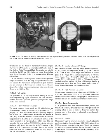
FIGURE 19.10 UV reactor for drinking water treatment. (a) Pipe segment showing electric connections. (b) UV tubes oriented parallel to
flow in pipe segment. (Courtesy of Kevin Gertig, Fort Collins, CO.)
installations and the latter in wastewater treatment. Figure 19.4.5.3.2 Medium-Pressure UV Lamps
19.10 shows a UV reactor as installed in 2003 in the City of The ‘‘medium-pressure’’ mercury lamps operate at pressure,
Fort Collins Water Treatment Plant. The reactor is a retrofit, 1 p 10 atm, and temperature, 5008C T 8008C (Snicer
installed in the 305 mm (12 in.) diameter return-flow pipeline et al., 2000, p. 18). These lamps emit radiation at several
from the solids settling basin, in a segment about 450 mm peaks in the range 240 l(medium pressure) 580 nm
(18 in.) long. (from Figure 19.6, 100 < l(UV) < 400 nm). The bulb life
In UV reactors for drinking water, those with low-pressure ranges, 2000 t(life-span) 5000 h. Although the power
lamps are oriented with the lamp axis parallel to the flow. required to deliver a given UV dose is higher than that for a
UV reactors for wastewater are typically in open channels low-pressure lamp, there are fewer lamps, and the cost of
and are oriented in horizontal or vertical banks. Reactor lamps, lamp replacement, and cleaning are less.
designs for medium-pressure reactors vary in the same fashion
(Snicer et al., 2000, p. 20).
19.4.5.3.3 High-Pressure UV Lamps
19.4.5.3 UV Lamps High-pressure lamps operate at p(lamp gas) 1000 kPa, that
is, 10 atm (Masschelein, 2002, p. 14). They emit continuous
The generation of UV by lamps involves passing an electric
spectra of radiation in a range not appropriate for disinfection
arc through mercury vapor. Three kinds are ‘‘low-pressure,’’
and thus they are not used to any extent in water treatment.
medium-pressure,’’ ‘‘pressure–pressure’’; low-pressure lamps
are the most common.
19.4.5.4 Lamp Components
19.4.5.3.1 Low-Pressure UV Lamps A UV system has three main components: lamps, sleeves, and
The most common lamps used for UV disinfection are ballasts. In addition, the lamps must have the provision for
‘‘low-pressure’’ having a mercury vapor pressure, 10 3 cleaning either in situ or removed from the reactor. The
p(Hg) 10 2 mm Hg with the surface operating tempera- cleaning may be done either by chemicals or mechanically
ture of 408C–508C; and as noted by DeMers and Renner in by using brushes.
1992, they mimic the behavior of conventional fluorescent
lamps (Snicer et al., 2000, p. 18). About 0.85 fraction of the 19.4.5.4.1 Sleeves
energy emitted is at wavelength, l ¼ 253.7 nm. The life The mercury vapor in lamps are encased in clear, fused quartz
span of a UV lamp is about 7500–8800 h, with the intensity envelopes, that is, sleeves that pass 0.85–0.90 fraction of the
decliningwithtime, forexample,to0.75fraction ofits 253.7 nm energy generated by the lamp. The air gap between
output at 0 h. Low-pressure mercury lamps are usually the bulb and the sleeve insulates the gas, thermally, from the
flowing water. The water pressure limit is, p(water) 1034
cylindrical, with 0.9 diameter 4cm,and10 length
160 cm (Masschelein, 2002, p. 15). kPa (150 psi).