Page 679 - Fundamentals of Water Treatment Unit Processes : Physical, Chemical, and Biological
P. 679
634                            Fundamentals of Water Treatment Unit Processes: Physical, Chemical, and Biological


            filtration to give an average dose, C(O 3 )   1.5 mg=L. Disin-  Required
            fection takes place in four reactors where ozone is diffused by  (a) Calculate the rate of chlorine feed into the
            porous plates, with u(avg)   12 min. At the end of the  solution feeder. (b) Calculate the maximum concentra-
            reactors, C(O 3 )   0.4 mg=L, which is the setpoint for control;  tion of HOCl in the solution feeder. (c) Assuming the
            if a higher level is detected, the ozone dosage is reduced and  maximum concentration of chlorine in the solution-
            vice versa. After ozone, chlorine is added for both secondary  feeder, determine the associated solution feeder flow,
            disinfection and maintaining a residual in the distribution  Q(solution).
            system, C(Cl 2 )   0.4 mg=L (Langlais, 1991, p. 229). As to  19.2 Estimating Hypochlorite Concentration of Giardia
            the effectiveness of ozone disinfection, data provided by  Cyst Inactivation
            Langlais (1991, p. 230) showed significant reductions of  Given
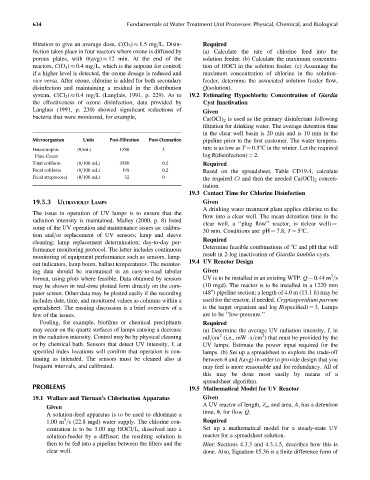
            bacteria that were monitored, for example,              Ca(OCl) 2 is used as the primary disinfectant following
                                                                    filtration for drinking water. The average detention time
                                                                    in the clear well basin is 20 min and is 10 min in the
            Microorganism   Units    Post-Filtration  Post-Ozonation  pipeline prior to the first customer. The water tempera-
                                                                    ture is as low as T ¼ 0.58C in the winter. Let the required
            Heterotrophic  (#=mL)       1580          3
             Plate Count                                            log R(disinfection) ¼ 2.
            Total coliform  (#=100 mL)  3580          0.2           Required
            Fecal coliform  (#=100 mL)   198          0.2           Based on the spreadsheet, Table CD19.4, calculate
            Fecal streptococci  (#=100 mL)  32        0             the required Ct and then the needed Ca(OCl) 2 concen-
                                                                    tration.
                                                               19.3 Contact Time for Chlorine Disinfection
            19.5.3 ULTRAVIOLET LAMPS                                Given
                                                                    A drinking water treatment plant applies chlorine to the
            The issue in operation of UV lamps is to ensure that the
                                                                    flow into a clear well. The mean detention time in the
            radiation intensity is maintained. Malley (2000, p. 8) listed
            some of the UV operation and maintenance issues as: calibra-  clear well, a ‘‘plug flow’’ reactor, is t(clear well) ¼
                                                                    30 min. Conditions are: pH ¼ 7.8, T ¼ 58C.
            tion and=or replacement of UV sensors; lamp and sleeve
                                                                    Required
            cleaning; lamp replacement determination; day-to-day per-
                                                                    Determine feasible combinations of 8C and pH that will
            formance monitoring protocol. The latter includes continuous
                                                                    result in 2-log inactivation of Giardia lamblia cysts.
            monitoring of equipment performance such as sensors, lamp-
                                                               19.4 UV Reactor Design
            out indicators, lamp hours, ballast temperatures. The monitor-
            ing data should be maintained in an easy-to-read tabular  Given
                                                                                                              3
            format, using plots where feasible. Data obtained by sensors  UV is to be installed in an existing WTP. Q ¼ 0.44 m =s
            may be shown in real-time plotted form directly on the com-  (10 mgd). The reactor is to be installed in a 1220 mm
            puter screen. Other data may be plotted easily if the recording  (48 ) pipeline section; a length of 4.0 m (13.1 ft) may be
                                                                      00
            includes date, time, and monitored values as columns within a  used for the reactor, if needed. Cryptosporidium parvum
            spreadsheet. The ensuing discussion is a brief overview of a  is the target organism and log R(specified) ¼ 3. Lamps
            few of the issues.                                      are to be ‘‘low-pressure.’’
              Fouling, for example, biofilms or chemical precipitants  Required
            may occur on the quartz surfaces of lamps causing a decrease  (a) Determine the average UV radiation intensity, I,in
                                                                                       2
                                                                         2
            in the radiation intensity. Control may be by physical cleaning  mJ=cm (i.e., mW   s=cm ) that must be provided by the
            or by chemical bath. Sensors that detect UV intensity, I,at  UV lamps. Estimate the power input required for the
            specified index locations will confirm that operation is con-  lamps. (b) Set up a spreadsheet to explore the trade-off
            tinuing as intended. The sensors must be cleaned also at  between u and I(avg) in order to provide design that you
            frequent intervals, and calibrated.                     may feel is more reasonable and for redundancy. All of
                                                                    this may be done most easily by means of a
                                                                    spreadsheet algorithm.
            PROBLEMS                                           19.5 Mathematical Model for UV Reactor
            19.1 Wallace and Tiernan’s Chlorination Apparatus       Given
                                                                    A UV reactor of length, Z o , and area, A, has a detention
                Given
                                                                    time, u, for flow Q.
                A solution-feed apparatus is to be used to chlorinate a
                      3
                1.00 m =s (22.8 mgd) water supply. The chlorine con-  Required
                centration is to be 3.00 mg HOCl=L, dissolved into a  Set up a mathematical model for a steady-state UV
                solution-feeder by a diffuser; the resulting solution is  reactor for a spreadsheet solution.
                then to be fed into a pipeline between the filters and the  Hint: Sections 4.3.3 and 4.3.4.5, describes how this is
                clear well.                                         done. Also, Equation 15.36 is a finite difference form of

