
Page 674 - Fundamentals of Water Treatment Unit Processes : Physical, Chemical, and Biological
P. 674
Disinfection 629
19.4 DESIGN considered as causing an increased transport hazard and may
be perceived as a nuisance to neighbors (depending on cir-
The heart of any design is the ‘‘reactor,’’ which brings into
cumstances). On the other hand, a lot of storage, for example,
contact the disinfectant and the organism. The reactor and its
more than several months, could be more costly than desired
appurtenances comprise the ‘‘system.’’ The system, for
since the metering and storage requires special design to
example, chlorine, hypochlorite, ozone, chlorine dioxide, UV,
reduce the risks associated with chlorine use, and for security.
may be ‘‘packaged,’’ in part or whole, as proprietary equipment.
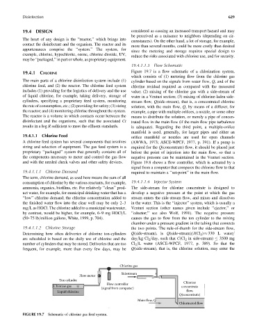
19.4.1.1.3 Flow Schematic
Figure 19.7 is a flow schematic of a chlorination system,
19.4.1 CHLORINE
which consists of (1) metering flow from the chlorine gas
The main parts of a chlorine disinfection system include (1) cylinder based on the signals from water flow, Q, and of the
chlorine feed, and (2) the reactor. The chlorine feed system chlorine residual required as compared with the measured
includes (1) providing for the logistics of delivery and the use value; (2) mixing of the chlorine gas with a side-stream of
of liquid chlorine, for example, taking delivery, storage of water in a Venturi section; (3) mixing of chlorine-laden side-
cylinders, specifying a proprietary feed system, monitoring stream flow, Q(side-stream), that is, a concentrated chlorine
the rate of consumption, etc.; (2) providing for safety; (3) sizing solution, with the main flow, Q, by means of a diffuser, for
the reactor; and (4) monitoring chlorine throughout the system. example, a pipe with multiple orifices, a nozzle, or some other
The reactor is a volume in which contacts occur between the means to distribute the solution, or merely a pipe of concen-
disinfectant and the organisms, such that the associated Ct trated flow in the main flow (if the main flow pipe turbulence
results in a log R sufficient to meet the effluent standards. is adequate). Regarding the third point, a multiple-orifice
manifold is used, generally, for larger pipes and either an
19.4.1.1 Chlorine Feed orifice manifold or nozzles are used for open channels
A chlorine feed system has several components that involves (AWWA, 1973; ASCE-WPCF, 1977, p. 391). If a pump is
sizing and selection of equipment. The gas feed system is a required for the Q(concentrate) flow, it should be placed just
proprietary ‘‘packaged’’ system that generally contains all of before the point of injection into the main flow, so that a
the components necessary to meter and control the gas flow negative pressure can be maintained in the Venturi section.
and with the needed check valves and other safety devices. Figure 19.8 shows a flow controller, which is actuated by a
signal from a computer that compares the chlorine flow to that
19.4.1.1.1 Chlorine Demand required to maintain a ‘‘set-point’’ in the main flow.
The term, chlorine demand, as used here means the sum of all
consumption of chlorine by the various reactants, for example, 19.4.1.1.4 Injector System
ammonia, organics, biofilms, etc. For relatively ‘‘clean’’ prod- The side-stream for chlorine concentrate is designed to
uct water, for example, for municipal drinking water that has a develop a negative pressure at the point at which the gas
‘‘low’’ chlorine demand; the chlorine concentration added to stream enters the side-stream flow, and mixes and dissolves
the finished water flow into the clear well may be only 2–3 in the water. This is the ‘‘injector’’ system, which is usually a
mg=L as HOCl. The chlorine added to a municipal wastewater, Venturi section (other names given include ‘‘ejector,’’ or
by contrast, would be higher, for example, 6–9 mg HOCl=L ‘‘eductor;’’ see also Wolf, 1991). The negative pressure
(50–75 lb=million gallons, White, 1999, p. 704). causes the gas to flow from the ton cylinder to the mixing
chamber under a pressure gradient in the tubing that connects
19.4.1.1.2 Chlorine Storage the two points. The rule-of-thumb for the side-stream flow,
Determining how often deliveries of chlorine ton-cylinders Q(side-stream), is Q(side-stream)=J(Cl 2 ) 330 L water=
are scheduled is based on the daily use of chlorine and the day=kg Cl 2 =day, such that C(Cl 2 in side-stream) 3500 mg
number of cylinders that may be stored. Deliveries that are too Cl 2 =L water (ASCE-WPCF, 1977, p. 389). So that the
frequent, for example, more than every few days, may be Q(side-stream), that is, the chlorine solution, may enter the
Chlorine gas
Sidestream
Flow meter
Ton cylinder
Chlorine
Flow controller
Chlorine gas concentrate
(signal from computer)
Liquid chlorine flow,
Q(concentrate)
Main flow, Q
Chlorinated flow
FIGURE 19.7 Schematic of chlorine gas feed system.