Page 778 - Fundamentals of Water Treatment Unit Processes : Physical, Chemical, and Biological
P. 778
Biological Reactors                                                                              733


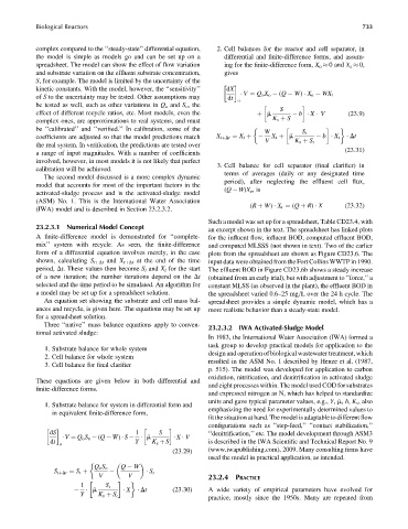
            complex compared to the ‘‘steady-state’’ differential equation,  2. Cell balances for the reactor and cell separator, in
            the model is simple as models go and can be set up on a  differential and finite-difference forms, and assum-
            spreadsheet. The model can show the effect of flow variation  ing for the finite-difference form, X o   0 and X e   0,
            and substrate variation on the effluent substrate concentration,  gives
            S, for example. The model is limited by the uncertainty of the

            kinetic constants. With the model, however, the ‘‘sensitivity’’  dX
                                                                           V ¼ Q o X o   (Q   W)   X e   WX r
            of S to the uncertainty may be tested. Other assumptions may  dt
                                                                        o
            be tested as well, such as other variations in Q o and S o , the
                                                                                     S
            effect of different recycle ratios, etc. Most models, even the    þ ^m        b   X   V      (23:9)
            complex ones, are approximations to real systems, and must            K s þ S
            be ‘‘calibrated’’ and ‘‘verified.’’ In calibration, some of the
                                                                                W          S t
            coefficients are adjusted so that the model predictions match  X tþDt ¼ X t þ   X r þ ^m    b   X t    Dt
                                                                                V        K s þ S t
            the real system. In verification, the predictions are tested over
                                                                                                        (23:31)
            a range of input magnitudes. With a number of coefficients
            involved, however, in most models it is not likely that perfect
                                                                  3. Cell balance for cell separator (final clarifier) in
            calibration will be achieved.
                                                                    terms of averages (daily or any designated time
              The second model discussed is a more complex dynamic
                                                                    period), after neglecting the effluent cell flux,
            model that accounts for most of the important factors in the
                                                                    (Q   W)X e ,is
            activated-sludge process and is the activated-sludge model
            (ASM) No. 1. This is the International Water Association
                                                                            (R þ W)   X r ¼ (Q þ R)   X  (23:32)
            (IWA) model and is described in Section 23.2.3.2.
                                                               Such a model was set up for a spreadsheet, Table CD23.4, with
            23.2.3.1  Numerical Model Concept                  an excerpt shown in the text. The spreadsheet has linked plots
            A finite-difference model is demonstrated for ‘‘complete-  for the influent flow, influent BOD, computed effluent BOD,
            mix’’ system with recycle. As seen, the finite-difference  and computed MLSSS (not shown in text). Two of the earlier
            form of a differential equation involves merely, in the case  plots from the spreadsheet are shown as Figure CD23.6. The
            shown, calculating S tþDt and X tþDt at the end of the time  input data were obtained from the Fort Collins WWTP in 1990.
            period, Dt. These values then become S t and X t for the start  The effluent BOD in Figure CD23.6b shows a steady increase
            of a new iteration; the number iterations depend on the Dt  (obtained from an early trial), but with adjustment to ‘‘force,’’ a
            selected and the time period to be simulated. An algorithm for  constant MLSS (as observed in the plant), the effluent BOD in
            a model may be set up for a spreadsheet solution.  the spreadsheet varied 0.6–25 mg=L over the 24 h cycle. The
              An equation set showing the substrate and cell mass bal-  spreadsheet provides a simple dynamic model, which has a
            ances and recycle, is given here. The equations may be set up  more realistic behavior than a steady-state model.
            for a spreadsheet solution.
              Three ‘‘native’’ mass balance equations apply to conven-  23.2.3.2  IWA Activated-Sludge Model
            tional activated sludge:
                                                               In 1983, the International Water Association (IWA) formed a
                                                               task group to develop practical models for application to the
              1. Substrate balance for whole system
                                                               design and operation of biological wastewater treatment, which
              2. Cell balance for whole system
                                                               resulted in the ASM No. 1 described by Henze et al. (1987,
              3. Cell balance for final clarifier
                                                               p. 515). The model was developed for application to carbon
                                                               oxidation, nitrification, and denitrification in activated sludge
            These equations are given below in both differential and
                                                               and eight processes within. The model used COD for substrates
            finite-difference forms.
                                                               and expressed nitrogen as N, which has helped to standardize
                                                               units and gave typical parameter values, e.g., Y, ^m, b, K s , also
              1. Substrate balance for system in differential form and
                                                               emphasizing the need for experimentally determined values to
                 in equivalent finite-difference form,
                                                               fit the situation at hand. The model is adaptable to different flow
                                                               configurations such as ‘‘step-feed,’’ ‘‘contact stabilization,’’

                dS                       1      S              ‘‘denitrification,’’ etc. The model development through ASM3
                     V ¼ Q o S o   (Q   W)   S     ^m    X   V
                dt                       Y    K s þ S          is described in the IWA Scientific and Technical Report No. 9
                   o
                                                     (23:29)   (www.iwapublishing.com), 2009. Many consulting firms have
                                                               used the model in practical application, as intended.

                             Q o S o  Q   W
                                               S t
                 S tþDt ¼ S t þ
                              V        V                       23.2.4 PRACTICE

                         1       S t
                             ^m         X    Dt      (23:30)   A wide variety of empirical parameters have evolved for
                         Y    K s þ S t

                                                               practice, mostly since the 1950s. Many are repeated from

