
Page 774 - Fundamentals of Water Treatment Unit Processes : Physical, Chemical, and Biological
P. 774
Biological Reactors 729
the previous sections). Equation 23.11 gives the required cell 23.2.2.3.3 Cell Mass Balance
wastage rate, and Equation 23.54 gives the recirculation ratio Circumscribing the system, i.e., the reactor and clarifier,
in terms of needed X. W ¼ 0, assume steady state, dQ=dt ¼ 0, and let X o ! 0, to
The needed X relates back to kinetic analysis; higher X give a resultant mass balance,
results in higher reaction velocity. Higher values of X in the
reactor are achievable by achieving a higher cell concentra-
dX
tion, X r , in the final clarifier underflow, or by increasing V ¼ QX e þ (m b)XV (23:15)
dt
the R=Q ratio. Increasing the R=Q ratio is not a good o
approach, however, since it decreases the effective hydraulic
detention time, u, i.e., the value for u should be calculated as In other words, if the mass flow of viable cells leaving the
u ¼ V=(Q þ R), not u ¼ V=Q. The latter is a simplifying clarifier is higher than the net cell production rate, the cell
assumption that permits illustration of relationships. A modi- concentration in the reactor will decrease with time. By the
fication to the equation shown and solved on a spreadsheet same token, decreasing the mass flow, Q X e , leaving the
provides a more accurate calculation of u. clarifier will cause an increase of cells in the reactor.
As a matter of interest, because of the uncertainty in the Next impose [dX=dt] o ¼ 0, which means that at steady state
values of the kinetic constants, i.e., ^m and K s , it is more the observed rate of change in the reactor is zero, meaning that
expedient in practice to size the reactor, V(reactor), based on the mass flux of cells leaving the reactor equals the net rate of
what is known to work through decades of experience, e.g., cell synthesis. Divide by Q, to give
u 6 h. When dealing with industrial wastes, the kinetics may
warrant a selecting of different value for u, usually based on X e ¼ (m b)Xu (23:16)
pilot plant work or experience within the industry.
23.2.2.3.4 Cell Recycle
23.2.2.3 Extended Aeration To determine, R, to maintain a required X, the materials
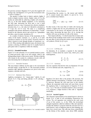
Figure 23.3 is the schematic for an extended aeration system. balance is written about the reactor only, which gives, after
As noted previously, there is no cell wasting, which is the rearrangement,
distinguishing feature of this reactor mode. The idea is that the
cells remain in the system by continuous recycle with cell R X X e
(23:17)
mass decreasing due to endogenous respiration. Q ¼ X r X
23.2.2.3.1 Extended Aeration 23.2.2.3.5 Summary
The mass balance relations are the same as for conventional The two equations that tell the story are Equations 23.6 and
activated sludge, except that W ¼ 0. The associated resultant 23.16 for substrate and cells, respectively, i.e.,
equations after applying assumptions are given in the same
sequence, substrate and cells. m
Y
(S o S) ¼ Xu (23:6)
23.2.2.3.2 Substrate Mass Balance X e ¼ (m b)Xu (23:18)
Applying assumptions: for ‘‘steady-state,’’ dQ=dt ¼ 0, and
Equation 23.6 shows that as the product, Xu, increases, the
dS o =dt ¼ 0, u ¼ V=Q, and letting, [dS=dt] ¼ (1=Y) [dX=dt] g ¼
(m=Y) X, effluent substrate concentration, S, declines; at the same time,
X e increases. Because the cells must leave in the clarifier
m effluent, the suspended solids limits will most likely exceed
Xu (23:6)
Y
(S o S) ¼ the regulatory limit. A rearrangement of Equation 23.18, is
u=u c ¼ X e =X. The idea of extended aeration is that b increases
as u c increases; a larger fraction of the cells is ‘‘digested’’
aerobically.
Clarifier
Reactor
23.2.2.4 Aerated Lagoon
Q S Q+ R Q The schematic representation of an aerated lagoon is shown in
X
S o V S S Figure 23.4. A lack of cell recirculation characterizes the
X
X o X e system. The cell separation was omitted in the early years
of use of this system, i.e., in the 1960s, but increasingly
R
R X r stringent regulations called for addition of this unit operation.
Usually the clarifier is a pond in which the cell removal is by a
X r
batch process, such as bulldozer removal after draining, per-
FIGURE 23.3 Schematic representation of an extended aeration haps every several years. The cells may decay anaerobically
system. on the bottom of the clarifier; since about 2000, methane