Page 775 - Fundamentals of Water Treatment Unit Processes : Physical, Chemical, and Biological
P. 775

730                            Fundamentals of Water Treatment Unit Processes: Physical, Chemical, and Biological


                         Reactor                                      S n


               Q           S         Q         Clarifier  Q
                           X
              S o          V          S         pond      S           S
              X o                     X                  X e

                                                                      0
            FIGURE 23.4  Aerated lagoon schematic.                     0            Z

                                                                                                         Q S X
                                                                 Q S o  X o
            emissions have been considered not acceptable. Separating
            the cells and sending to a digester would be a more contem-
            porary solution.
              The mass balance relations are the same as for conven-                 ΔZ
            tional activated sludge, except that W ¼ 0. The associated
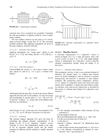
                                                               FIGURE 23.5  Schematic representation of a plug-flow reactor
            resultant equations after applying assumptions are given in
                                                               (clarifier not shown).
            the same sequence, substrate, and cells.
            23.2.2.4.1  Substrate Mass Balance
            Applying assumptions: for ‘‘steady state,’’ dQ=dt ¼ 0 and  23.2.2.5  Plug-Flow Reactor
                                                               A schematic representation of a ‘‘plug-flow’’ reactor is
            dS o =dt ¼ 0, u ¼ V=Q, and letting, [dS=dt] ¼ (1=Y)   [dX=dt] g ¼
            (m=Y)   X,                                         shown in Figure 23.5; it is a long and narrow basin with
                                                               a cross section of about 5 m   5 m, with length perhaps
                                       m                       100 m. A characteristic of a ‘‘plug-flow’’ reactor is that the
                                         Xu             (23:6)
                                       Y                       substrate concentration declines along the length, Z,of
                              (S o   S) ¼
                                                               the reactor.
            23.2.2.4.2  Cells Mass Balance
            Circumscribing the system, i.e., the reactor, assume steady  23.2.2.5.1  Substrate Mass Balance
            state, dQ=dt ¼ 0, and let X o ! 0, to give a resultant mass
                                                               The assumption, not true, is that a cross-sectional element of
            balance,
                                                               thickness, DZ, remains intact, i.e., without mass transfer
                                                               across its pseudo boundaries; such an element is assumed
                             QX ¼ (m   b)XV            (23:19)
                                                               homogeneous and therefore is amenable to mass balance
                                                               modeling. The packed-bed reactor mathematics, Section,
            or                                                 4.3.3.3, applies to a plug-flow reactor and shows the math-
                                                               ematics more completely. A steady-state mass balance model,
                                   1                           for substrate, cells, and recycle, respectively, is described in
                                          u c          (23:20)
                                 (m   b)                       this section. A substrate mass balance for a plug-flow cross
                             u ¼
                                                               section is
            which means that the mass flow of cells in the reactor effluent
            equals the net mass rate of cell synthesis. As seen, the reactor    q(S   DZ   A)
                                                           m
            cell concentration, X, cancels, and so, 1 ¼ (m   b)u,or u ¼ u .  ¼ [  vS in A     vS out A] þ [j A   j A]
                                                                                              in
                                                                                                   out
                                                           c        qt
            To prevent ‘‘washout,’’ i.e., losing cells in the effluent faster  o
                                                                                 q(S   DZ   A)
            than they are reproduced,                                                                     (23:22)
                                                                                     qt
                                                                              þ
                                                                                            r
                                 u   u m               (23:21)
                                      c
                                                               where
                            m
            and in design, u   u . At the same time, from Equation 23.6,  S is the substrate concentration within element, DZ (kg
                            c
                                                                             3
            i.e., (S o   S) ¼ (m=Y)   Xu, then S decreases as u increases.  substrate=m )
                                                                  Z is the length of basin (m)
            23.2.2.4.3  Summary                                   DZ is the infinitesimal basin length, i.e., a ‘‘slice’’ (m)
                                                                                                  2
            The substrate balance, Equation 23.6, gives the basis for  A is the cross-sectional area of basin (m )
            calculating the effluent substrate concentration, S.In  t is the time (s)
                       m
                                 m
            design, u   u ;if u < u , organism ‘‘washout’’ occurs.  subscript o denotes ‘‘observed’’ for infinitesimal basin
                       c         c
            Typically u   24 h. The mathematical model is the same  volume, DZA
            as for an anaerobic digester except that the kinetic  v is the average velocity along length basin, i.e., Q=A (m=s)
            constants are different and the substrate is usually measured  S in is the substrate concentration at entrance to cross-
                                                                                              3
            as VSS.                                                 sectional ‘‘slice’’ (kg substrate=m )
   770   771   772   773   774   775   776   777   778   779   780