
Page 772 - Fundamentals of Water Treatment Unit Processes : Physical, Chemical, and Biological
P. 772
Biological Reactors 727
Reactors. Several kinds of reactors include complete-mix, is also ‘‘complete-mix,’’ since its shape is closer to square,
plug-flow, extended aeration, aerated lagoon, batch, sequen- whereas a ‘‘plug-flow’’ reactor is long and narrow in shape.
cing-batch, etc. The analysis of complete-mix and plug-flow The operator controls the process by maintaining a desired
is a basis for understanding variations. cell concentration, X, in the reactor, which is done by con-
trolling the R, the return flow, and W, the flow of waste
1. Complete-mix reactor. A turbine aeration systems is sludge.
‘‘completely mixed’’ because of the high rate of pump-
ing by the aerator. The assumption of a complete-mix 23.2.2.2.1 Substrate Balance
reactor is that the entering fluid is instantly mixed The substrate materials balance for the reactor and cell separ-
throughout the reactor, i.e., the reactor is homoge- ator in Figure 23.2 is
neous. The substrate concentration, S, in the reactor
effluent is the same within all parts of the reactor dS dS
V (23:3)
volume. The mass balance analysis for a ‘‘complete- dt o V ¼ QS o (Q W)S WS dt r
mix’’ reactor is developed first, i.e., prior to the ‘‘plug-
flow’’ reactor model, since it is simpler mathematically. where
2. Plug-flow reactor. For a plug-flow activated-sludge [dS=dt] o is the observed rate of change of substrate con-
reactor, such as for a diffused aeration system, the centration in the reactor (mg BOD=L=day)
volume is not homogeneous, since the substrate con- V is the volume of reactor (L)
centration, S, declines along its length. Therefore, the Q is the flow through the reactor (L=day)
reactor must be analyzed in terms of ‘‘slices,’’ which S o is the concentration of substrate in the influent flow;
are cross sections of finite thickness. It is not strictly measured as BOD, COD, TOC, etc, as convenient as
true that a ‘‘slice’’ is a homogeneous volume but long as other units are consistent (mg=L)
such an assumption simplifies the mass balance S is the concentration of substrate in the reactor (mg=L)
analysis. Another assumption is that longitudinal [dS=dt] r is the rate of substrate conversion reaction
dispersion is negligible, not true, but it simplifies (mg BOD=L=day)
the mathematical depiction.
3. Cell mass balance schemes. The premise of activated Equation 23.3 is completely general; note that the ‘‘RS’’
sludge as established by Ardern and Lockett is that the into the reactor cancels the ‘‘RS’’ out (and to be strictly correct
reactor must contain previously synthesized viable Equation 23.3 should have these terms). If carried through as
cells. These cells convert the organic substrate (the a finite-difference equation it could be solved for transient
waste material) to new cells as depicted in Section conditions. The ‘‘steady-state’’ approximation is usually
22.3.3.1. To maintain the needed cell concentration, imposed, however, which requires that the flow, Q, and sub-
X (or the surrogates, MLVSS or MLSS), three basic strate inflow concentration, S o , do not vary with time. There-
schemes are used: (a) cell separation, recycle, and fore, the observed rate of change of substrate concentration in
wasting; (b) cell separation, recycle, no wasting; and the reactor is zero, i.e., [dS=dt] o ¼ 0. The resulting steady-state
(c) no cell separation, no recycle, and no wasting. description is
These three schemes are called conventional recycle
activated sludge, extended aeration activated sludge, dS
V (23:4)
and aerated lagoon, respectively. The mathematical dt
0 ¼ Q(S o S)
r
depictions follow these descriptions.
Substituting the hydraulic detention time, u ¼ V=Q,
23.2.2.2 Conventional Activated Sludge
dS
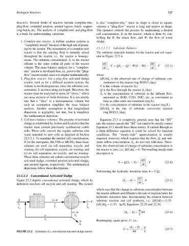
Figure 23.2 depicts conventional activated sludge, which by (S o S) ¼ u (23:5)
dt
definition involves cell recycle and cell wasting. The system r
which says that the change in substrate concentration between
Clarifier the reactor influent and effluent is the rate of reaction times the
Reactor
hydraulic detention time. Incorporating the relation between
Q S Q+R
X Q–W substrate reaction and cell synthesis, i.e., [dS=dt] ¼ (1=Y)
V
S o S S [dX=dt] g ¼ (1=Y) [mX], Equations 22.29 and 22.30,
X X
X o e
m
R+W (S o S) ¼ Xu (23:6)
R X r Y
X r
W Rearranging, again gives, U, i.e.,
X r
(S o S) m
(23:7)
U
FIGURE 23.2 Schematic of a conventional activated-sludge reactor. uX Y
¼