
Page 791 - Fundamentals of Water Treatment Unit Processes : Physical, Chemical, and Biological
P. 791
746 Fundamentals of Water Treatment Unit Processes: Physical, Chemical, and Biological
is necessary to rely upon guidelines from experience, where
which are rather sparse. A CFD simulation by Meroney VSS o is the volatile suspended solids concentration flow-
(2009) illustrated mixing patterns for various configurations ing into the reactor (mg=L)
of tank inflow points, which does provide an avenue for VSS is the volatile suspended solids concentration in the
rational design. reactor and flowing out (mg=L)
Mixing may be accomplished by gas recirculation, by V is the volume of reactor (L)
recirculating the sludge, or by a turbine mixer. Usually, the Q is the flow into or out of the reactor (L=day)
mixing requirement is satisfied as a part of the selection of [d(VSS o )=dt] o is the observed rate of change of VSS con-
proprietary equipment. This is selected also with the view centration in the reactor (mg=L=day)
toward not permitting grit to settle on the bottom of the [d(VSS)=dt] r is the reaction rate of VSS in the reactor
digester, which requires about 2.0 fps local velocity. (mg VSS destroyed=L=day)
23.4.3.6 Environmental Conditions For the steady-state assumption [d(VSS)dt] o ¼ 0; also for
As stated, methane bacteria have a rather narrow ecological simplicity in illustrating some other key ideas, dV=dt ¼ 0,
niche. First they are obligate anaerobes. While oxygen will giving
not kill the cells it will make them dysfunctional. Heavy
metals are toxic as they are to most organisms; toxic con- d(VSS)
0 ¼ Q VSS o Q VSS V (23:43)
centration levels have not been established. Proper pH is dt r
another highly important requirement. McCarty (1964b,
p. 123) stated that the reaction may proceed in the pH
Rearranging and substituting V ¼ Qu,
range of 6.6 pH 7.6, with an optimum range of 7.0
pH 7.2. To maintain this pH range an alkalinity level of
several thousand mg=L alkalinity as CaCO 3 is desirable, to d(VSS) ¼ [VSS o VSS]=u (23:44)
act as a buffer in pH control (McCarty, 1964b, p. 125). dt destroyed
23.4.3.7 Materials Balance: Kinetic Model
In other words, the rate of solids destroyed may be estimated
The materials-balance concept is applicable also to the anaer- by the difference between the inflow of VSS and the outflow
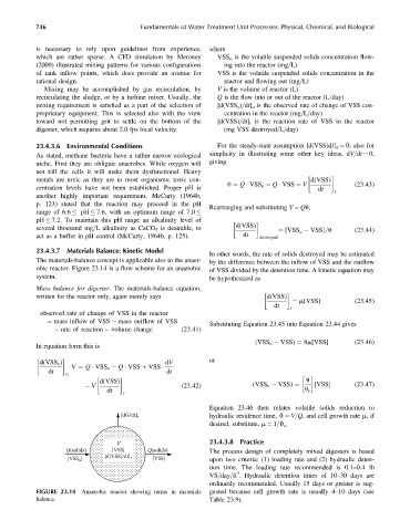
obic reactor. Figure 23.14 is a flow scheme for an anaerobic of VSS divided by the detention time. A kinetic equation may
system. be hypothesized as
Mass balance for digester. The materials-balance equation,
written for the reactor only, again merely says d(VSS)
¼ m[VSS] (23:45)
dt
r
observed rate of change of VSS in the reactor
¼ mass inflow of VSS mass outflow of VSS
Substituting Equation 23.45 into Equation 23.44 gives
rate of reaction volume change (23:41)
(VSS o VSS) ¼ um[VSS] (23:46)
In equation form this is
or
d(VSS o ) dV
dt V ¼ Q VSS o Q VSS þ VSS dt
o
d(VSS) u
V (23:42) (VSS o VSS) ¼ [VSS] (23:47)
dt u c
r
Equation 23.46 then relates volatile solids reduction to
[dG/dt] r hydraulic residence time, q ¼ V=Q, and cell growth rate m,if
desired, substitute, m ¼ 1=q c .
V 23.4.3.8 Practice
Q(solids) [VSS] Q(solids) The process design of completely mixed digesters is based
{d[VSS]/dt}
[VSS ] r [VSS] upon two criteria: (1) loading rate and (2) hydraulic deten-
o
tion time. The loading rate recommended is 0.1–0.4 lb
3
VS=day=ft . Hydraulic detention times of 10–30 days are
ordinarily recommended. Usually 15 days or greater is sug-
FIGURE 23.14 Anaerobic reactor showing terms in materials gested because cell growth rate is usually 4–10 days (see
balance. Table 23.9).