
Page 787 - Fundamentals of Water Treatment Unit Processes : Physical, Chemical, and Biological
P. 787
742 Fundamentals of Water Treatment Unit Processes: Physical, Chemical, and Biological
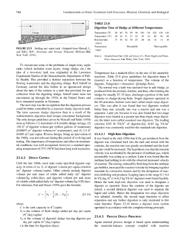
TABLE 23.8
Digestion Time of Sludge at Different Temperatures
Sludge Temperature (8F) 50 60 70 80 90 100 110 120 130 140
Temperature (8C) 10 16 21 27 32 38 43 49 54 60
Reaction time 75 56 42 30 25 24 26 16 14 18
(days)
Temperature Mesophillic Thermophillic
FIGURE 23.9 Settling and septic tank. (Adapted from Metcalf, L.
range
and Eddy, H.P., Sewerage and Sewage Disposal, McGraw-Hill,
New York, 1930.) Source: Adapted from Fair, G.M. and Geyer, J.C., Water Supply and Waste-
Water Disposal, John Wiley, New York, 1954.
To circumvent some of the problems of single-story septic
tanks (which included scum layers, rising sludge, etc.) the
idea of a two-story tank was originated at the Lawrence Temperature has a marked effect on the rate of the anaerobic
Experiment Station of the Massachusetts Department of Pub- reactions. Table 23.8 gives guidelines for digestion times u
lic Health. This provided a distinct separation between the (reactor) as a function of temperature. The volume of the
flowing wastewater and the digesting sludge. Karl Imhoff in digester, V(digester) ¼ u(reactor) Q(sludge flow).
Germany carried the idea further to an operational design The normal way a tank was operated was to add sludge, as
about the turn of the century in a tank that provided for gas produced from the primary clarifier, and then, after holding the
collection from the digesting sludge. Imhoff tanks were not sludge for usually 25–35 days, discharge a portion of the tank
uncommon up through the 1930s in the United States and contents to sludge-drying beds. Single digesters operated in
have remained popular in Germany. the fill-and-draw manner were later called single-stage digest-
The next step was the recognition that the digestion process ers. This was after it was found that two digesters worked
could be better controlled by a separate sludge digestion tank. better than one; actually one was a reactor and one was a
The term separate sludge digestion then is a result of the separator. Later yet, because it was also found that two-stage
sedimentation–digestion dual design conceptual background. digesters were loaded at a greater rate than single-stage digest-
The only design guidelines given by Metcalf and Eddy (1930) ers; the latter were called standard-rate digesters. The loading
3
were as follows: (1) maximum of 6 months sludge storage, (2) criterion 0.05 lb VS=ft of digester=day (0.81 kg VS=m 3
3
130 ft of digester volume per million gallons of wastewater digester) was commonly used for the standard-rate digesters.
3
3
(0.00097 m digester volume=m wastewater), and (3) 2.4 ft 3
3
(0.065 m ) per capita. Process design, being an innovation of 23.4.2.1 High-Rate Digestion
the 1960s, was not relevant during this period of evolving and It was found in the mid-1950s that if the gas produced from the
testing. The importance of temperature and other environmen- digester was circulated back into the tank and mixed with the
tal conditions was well recognized, however; a standard oper- contents, the reaction rate was greatly accelerated and the load-
ating temperature of 358C (968F) has been long used in practice. ing rate could be increased. The hypothesis was that the reaction
velocity was accelerated by the presence of methane gas, which
presumably was acting as a catalyst. Later it was found that the
23.4.2 DESIGN CRITERIA
methane had nothing to do with the observed increased velocity
Until the late 1960s, most state codes specified digester cap- of reaction. The mixing, induced by fluid drag from the methane
acity in terms of cu. ft. of digester volume per capita criterion gas bubbles, increased the reaction velocity by bringing together
3
(m digester volume=capita). Other criteria include digester reactants by convective motion and by the dissipation of reac-
3
volume per unit mass of solids added daily (m digester tion-inhibiting end products. Loading rates in the range 0.1–0.4
3
3
volume=kg solids=day), and digester volume per unit mass lb VS=day=ft (1.6–6.5 kg VS=m digester) were found feasible.
3
of volatile solids added daily (m digester volume=kg VSS=day). Hence the term high-rate digestion was used to designate a
For reference, Fair and Geyer (1954) gave the formula: digester so operated. Since the contents of the digester are
mixed, a second identical digester was used to separate the
2 liquid and solids. Hence the designation two-stage digestion
C ¼ V f (V f V d ) t (23:33)
3 was adopted. Actually, the second stage functions to effect
separation and any further digestion is only incidental to this
where main function. Figure 23.10 shows a digester cross section
3
C is the tank capacity in ft =capita operated in accordance with the complete-mixing principle.
V f is the volume of fresh sludge added per day per capita
3
(ft =day=capita)
23.4.3 PROCESS DESIGN PRINCIPLES
V d is the volume of digested sludge leaving digester per
3
day per capita (ft =day=capita) Again rational process design is based upon understanding
t is the time for digestion (days) the materials-balance concept coupled with reaction