
Page 856 - Fundamentals of Water Treatment Unit Processes : Physical, Chemical, and Biological
P. 856
Appendix D: Fluid Mechanics—Reviews of Selected Topics 811
TABLE D.7 TABLE D.8
Meter Coefficients for Flow Measurement Weir Coefficients for Flow Measurement
Meter Type Metering Formula d=D C D Meter Type Metering Formula H=P C w
0.5
Orifice Q ¼ C D A (2gDH) 0.5 0.10 0.60 Rectangular weir Q ¼ C w A (2g) w DH 0.5 0.00 0.40
0.20 0.60 0.10 0.405
0.30 0.60 0.20 0.41
0.40 0.62 0.30 0.415
0.50 0.63 0.40 0.42
0.60 0.65 0.50 0.43
0.70 0.70 0.60 0.43
0.80 0.77 0.80 0.44
Venturi Q ¼ C D A(throat) [2gDH] 0.5 0.50 1.00
Meter Type Metering Formula CV H
0.60 1.04 u
0.5
V-notch weir Q ¼ (8=15)C VH [2g] H 2.5 608 0.58
Notes: (1) D is diameter of pipe and d is diameter of orifice or Venturi Metric Q ¼ 0.79H 2.5 608 (H in m)
5 5
throat. (2) Coefficients are for R 10 ; for most flows, R 10 can U.S. Customary Q ¼ 1.44H 2.5 608 (H in ft)
5
be assumed. (3) For R < 10 can, the coefficient increases for orifices
3
3
and decreases for Venturi meters. Terms Q, flow in m =s (ft =s); C w , weir coefficient; g, acceleration of gravity
2
(9.81 m=s ).
Notes: (1) For a rectangular weir, C w ¼ 0.40 þ 0.05H=P. (2) For a V-notch
weir, C VN ¼ 0.58 when u ¼ 608. (3) General formulae work for SI
the pressure differential between upstream and downstream or U.S. Customary units.
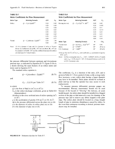
pressure taps, as indicated by Equation D.73. Figure D.10a is
a sketch showing the main features of an orifice meter and
terms used in Equation D.73.
The standard orifice equation is
The coefficient, C D , is a function of the ratio, d=D, and is
Q ¼ C d A(orifice) [2gDh] 1=2 (D:73) given in Table D.7. Over a period of time, as the average daily
flow increases, a new orifice plate having a larger diameter
and
may have to be installed. These plates should be on hand at
Þ per Table D:7 (D:74) plant start-up so that the operator has easy access to such
C D ¼ fd=Dð
replacements.
in which To measure pressure differential, pressure gauges are
3
3
Q is the flow of fluid in (m =s) or (ft =s) recommended. Mercury manometers should not be used
C D is the orifice discharge coefficient, given in Table D.8 because of the hazard of ‘‘blowing’’ the mercury, an acute
(dimensionless) health hazard. An orifice plate should be installed in a flanged
2
A(orifice) is the cross-sectional area of orifice opening (m ) section of the pipe so that removal is easy for cleaning of the
2
or (ft ) pressure taps and to remove any debris trapped at the plate
2
2
g is the acceleration of gravity (9.8 m=s ) or (32. ft=s ) edge. The orifice plate should be located in a long straight
Dh is the pressure differential across the plate (m) or (ft) length of pipe to minimize disturbances caused by eddies. In
d is the diameter of orifice in orifice plate (m) or (ft) the event that continuous recording is desired, pressure trans-
D is the diameter of pipe (m) or (ft) ducers may be installed.
d D d D
Manometer Manometer Δh
Δh
FIGURE D.10 Definition sketches for Table D.7.