
Page 854 - Fundamentals of Water Treatment Unit Processes : Physical, Chemical, and Biological
P. 854
Appendix D: Fluid Mechanics—Reviews of Selected Topics 809
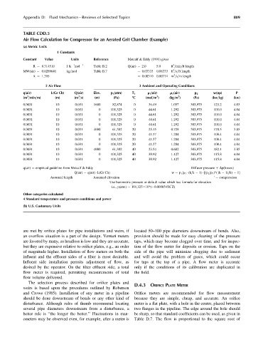
TABLE CDD.5
Air Flow Calculation for Compressor for an Aerated Grit Chamber (Example)
(a) Metric Units
1 Constants
Constant Value Units Reference Metcalf & Eddy (1991) gives
1
3
R ¼ 8.314510 J K mol 1 Table B.2 Q(air) ¼ 2.0 5.0 ft =min=ft length
3
MW(air) ¼ 0.0289641 kg=mol Table B.7 ¼ 0.03333 0.08333 ft =s=ft length
3
k ¼ 1.395 ¼ 0.00310 0.00774 m =s=m length
2 Air Flow 3 Ambient and Operating Conditions
q(air) L(Gr Ch) Q(air) Elev. p 1 (atm) T 1 r 1 (air) r 1 (air) p 2 w(op) P
3
3
3
3
(m =min=m) (m) (m =s) (m) (Pa) 8C (mol=m ) (kg=m ) (Pa) (kw=kg) (kw)
0.0031 10 0.031 1600 82,874 0 36.49 1.057 303,975 123.2 4.03
0.0031 10 0.031 0 101,325 0 44.61 1.292 303,975 101.0 4.04
0.0031 10 0.031 0 101,325 0 44.61 1.292 303,975 101.0 4.04
0.0031 10 0.031 0 101,325 0 44.61 1.292 303,975 101.0 4.04
0.0031 10 0.031 0 101,325 0 44.61 1.292 303,975 101.0 4.04
0.0031 10 0.031 4000 61,302 20 25.15 0.728 303,975 170.5 3.85
0.0031 10 0.031 0 101,325 20 41.57 1.204 303,975 108.4 4.04
0.0031 10 0.031 0 101,325 20 41.57 1.204 303,975 108.4 4.04
0.0031 10 0.031 0 101,325 20 41.57 1.204 303,975 108.4 4.04
0.0031 10 0.031 4000 61,302 40 23.54 0.682 303,975 182.1 3.85
0.0031 10 0.031 0 101,325 40 38.92 1.127 303,975 115.8 4.04
0.0031 10 0.031 0 101,325 40 38.92 1.127 303,975 115.8 4.04
q(air) ¼ empirical guideline from Metcalf & Eddy Diffuser pressure þ Dp(losses)
Q(air) ¼ q(air) L(Gr Ch) w ¼ p 1 =r 1 (k=k 1) [(p 2 =p 1 )^( (k 1)=k) 1]
Assumed length Assumed elevation ‘ ¼ compression
Use barometric pressure or default value which has formula for elevation
*
i.e., p(atm) ¼ 101,325 * 10^( 0.00005456 Z)
Other categories calculated
4 Standard temperature and pressure conditions and power
(b) U.S. Customary Units
are met by orifice plates for pipe installations and weirs, if located 50–100 pipe diameters downstream of bends. Also,
an overflow situation is a part of the design. Venturi meters provision should be made for easy cleaning of the pressure
are favored by many, as headloss is low and they are accurate, taps, which may become clogged over time, and for inspec-
but they are expensive relative to orifice plates, e.g., an order tion of the flow meter for deposits or erosion. Taps on the
of magnitude higher. Installation of flow meters on both the side of the pipe will minimize clogging due to sediment
influent and the effluent sides of a filter is most desirable. and will avoid the problem of gases, which could occur
Influent side installation permits adjustment of flow, as for taps at the top of a pipe. A flow meter is accurate
desired by the operator. On the filter effluent side, a total only if the conditions of its calibration are duplicated in
flow meter is required, permitting measurements of total the field.
flow volume delivered.
The selection process described for orifice plates and
D.4.3 ORIFICE PLATE METER
weirs is based upon the procedures outlined by Roberson
and Crowe (1985). Installation of any meter in a pipeline Orifice meters are recommended for flow measurement
should be done downstream of bends or any other kind of because they are simple, cheap, and accurate. An orifice
disturbance. Although rules of thumb recommend locating meter is a flat plate, with a hole in the center, placed between
several pipe diameters downstream from a disturbance, a two flanges in the pipeline. The edge around the hole should
better rule is ‘‘the longer the better.’’ Fluctuations in man- be sharp, so that standard coefficients can be used, as given in
ometers may be observed even, for example, after a meter is Table D.7. The flow is proportional to the square root of