Page 857 - Fundamentals of Water Treatment Unit Processes : Physical, Chemical, and Biological
P. 857
812 Appendix D: Fluid Mechanics—Reviews of Selected Topics
An alternate form of Equation D.73 that is used more ship with Dh for the abscissa and Q for the ordinate should
commonly for gas flow is be provided both as a plot and with proper coefficients for
the SCADA system used in most plants since the early
1=2 1990s. The operator should have the means to convert
(D:75)
Q ¼ C d A(orifice) Dp=r½
immediately the headloss, as read by pressure gauges or
in which piezometers, to flow.
2
Dp is the pressure loss across orifice (N=m )
3
r is the density of fluid (kg=m ) D.4.4 VENTURI METER
Note that Equations D.73 and D.75 are valid for any fluid, The Venturi meter requires less headloss than an orifice plate and
so may be more desirable when head is a major concern. Figure
liquid or gas.
D.9b is a sketch of a Venturi meter showing terms used in the
flow equation and the configuration of the manometer installa-
Example D.1 Orifice Plate Size tion. Note: The manometer used in the drawing to illustrate
pressure differential, pressure gauges, or transducers are recom-
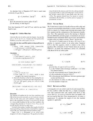
Calculate the size of orifice plate for Empire. Assume the mended because manometer fluids may be toxic and should be
pipe is 30.54 cm (12 in.). Assume also that permissible avoided as they are subject to being ‘‘blown’’ into the flow.
headloss across the orifice plate is 60 cm.
The cost of a Venturi meter to fit into a 30.5 cm (12 in.)
Given data for slow sand filter plant serving small town in pipeline is expensive relative to an orifice plate. Equation
Colorado D.76 is the flow equation, which is similar to the orifice
1. Q(max, 1,000 persons) ¼ 3028 L=person=day equation. The coefficients for the Venturi meter are given in
1,000 persons ¼ 3,028,000 L=day
Table D.7. As noted, the coefficient is about 1.0, contrasted
( ¼ 800 gpcd 1,000 persons ¼ 800,000 gal=day)
with about 0.6 for an orifice plate.
Calculation 1=2
1. First trial. Q ¼ C v A t (2gDh) (D:76)
a. From Table D.7, select C D ¼ 0.62
b. Calculate using Equation (D.73) and
Q ¼ 0:62 A(orifice) (2gh) 1=2 C v ¼ fd=Dð Þ (D:77)
3028=24=3600 ¼ 0:62 p(d)2=4(2 9:8 0:60)1=2 in which
½
3
3
Q is the flow of water in (m =s) or (ft =s)
d ¼ 0:14 m (5:7in:)
C v is the Venturi meter discharge coefficient ¼ 1.0, Table
D.8 (dimensionless)
2. Check C D . 2
a. d=D ¼ 0.14=0.35 ¼ 0.4 A t is the cross-sectional area of Venturi throat (m )
2
b. From Table D.7, C D ¼ 0.615, which is close g is the acceleration of gravity (9.81=s )
enough to the original assumption. Dh is the pressure head difference between upstream pipe
3. Determine headloss at the low flow during the sea- section and throat (m)
son of minimum demand and with 500 persons, i.e., d is the diameter of orifice in orifice plate (m)
278 Lcd (100 gpcd), giving Q ¼ 189,250 L=day D is the diameter of pipe (m)
(50,000 gpd).
189=24=3600 ¼ 0:62 p(0:14)2=4(2 9:8 h)1=2 D.4.5 RECTANGULAR WEIR
½
Dh ¼ 0:003 m or 3 mm (0:12 in:) A rectangular weir can control water levels and measure flow.
For the overflow within the filter box, a simple rectangular
weir with contracted ends will control water level so that
Discussion excess flow (i.e., in excess of what the filter can handle) will
This amount of headloss for the low flow condition is too
little to be measured accurately, so we must use a smaller not over-top the filter box. Flow measurement is, of course, a
orifice for the early years and substitute a larger orifice requirement. To calculate the length of weir, the standard
plate as the population increases. If we select say 50 mm equation is applicable:
as a measurable headloss for the low flow condition, the
corresponding diameter is 70 mm (2.75 in.). Thus, we will p ffiffiffiffiffi 1:5
Q ¼ C w 2gwH (D:78)
use this smaller size for the early years.
For both orifice plates, headloss-flow graphs should be
in which
drawn permitting a determination of desired flow range for
each of the two, based upon desired headloss range.
Figure D.9a is a photograph of an orifice plate, C w ¼ 0:40 þ 0:05 H (D:79)
designed to fit into a flanged pipe. The graphical relation- P

