Page 853 - Fundamentals of Water Treatment Unit Processes : Physical, Chemical, and Biological
P. 853
808                                                Appendix D: Fluid Mechanics—Reviews of Selected Topics


            Equation D.69 is the form given by McCabe et al. (1993,  .  A pressure, p 2 , on the discharge of the compressor
            p. 211). It was derived here since it a common reference.  was assumed for the purpose of demonstrating the
              In conversion to U.S. Customary units, the equation is the  working of the spreadsheet.
            same but the terms are in U.S. Customary units. Equation  . Temperature must be assumed.
            D.67 is repeated, i.e.,                               . Spreadsheet then calculates power for adiabatic com-
                                                                    pression by the equations described previously.
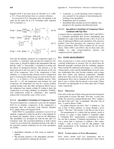
                                      "             #
                                            (k 1=k)
                         n(stp)    k     p 2                   D.3.5.5  Spreadsheet Calculation of Compressor Power
            P(stp) ¼ Q(stp)   RT 1                1    (D:70)
                         V(stp)  k   1   p 1                            Combined with Pipe Flow
                                                               A sequel to the two spreadsheets, Tables CDD.3 and CDD.5,
                                                   k
                          1:0 lb-mol 1544 ft-lb f              is a combined spreadsheet that involves determining pipe
            P(stp) ¼ Q(stp)     3              T 1
                           359 ft   lb-mol 8R    k   1         diameters for a pipe system that provides a flow of air to an
                     "            #
                           (k 1)=k                             array of submerged diffusers and calculation of the pressures
                        p 2
                                 1                     (D:71)  required. From these pressures, the compressor power can

                                                               then be determined. Table CDD.6 combines the two spread-
                        p 1
                                                               sheets, Tables CDD.3 and CDD.5, that do these tasks indi-
                                       "            #
                                             (k 1)=k
                                    k     p 2                  vidually,  i.e.,  pipe  sizing=compressor  pressure  and
                                                   1   (D:72)
            P(stp) ¼ 4:30   Q(stp)   T 1
                                  k   1   p 1                  compressor power, respectively.
                                                               D.4 FLOW MEASUREMENT
            Note that the adiabatic equations for compression apply to a
            reversible, i.e., isentropic, path and that the compressor effi-  Flow measurement is a basic need in plant operation. Con-
            ciency term, h, should be added to the denominator (the fact  ventional technologies to measure flow are based upon the
            that the ‘‘path’’ is ‘‘irreversible’’ is included in h along with  Bernoulli principle combined with the continuity equation.
            the effects of mechanical friction). The pressure p 1 is the  These include the traditional technologies, i.e., orifice plates,
            intake pressure in this case and p 2 is the pressure on the exit  Venturi meters, weirs, and the Parshall flume. In recent years,
            side of the compressor. Also, if the compression is truly  new technologies have also become common, such as mag-
            adiabatic, i.e., no heat transfer, then the work of compression  netic flow meters and electrical conductance. Propeller
            goes to increasing the internal energy (as seen by the first law,  meters have been used for many years in pipes, both to give
            DE ¼ q   w, in which q ¼ 0 for an adiabatic process. Thus,  instantaneous flows and to integrate the flows over a given
            since DE ¼ c v   DT, the temperature must increase. In a real  time to give a volume that has passed a given point. Figure
            compressor, the temperature rise may be a serious problem  D.9a and b are photographs of an orifice plate and a Venturi
            (causing bearing wear and other mechanical effects) and so  meter, respectively.
            the compressor may require cooling. If cooling is done, the
            compression is no longer adiabatic, by definition. Probably,  D.4.1 DEFINITIONS
            such compression would be ‘‘polytropic,’’ thus requiring
                                                               Flow refers to the rate of fluid volume per unit time that passes
            analysis that is beyond the scope of this review.
                                                               a given point or section. The term ‘‘flow rate’’ is used com-
                                                               monly, but some have asserted that the term ‘‘flow’’ implies a
            D.3.5.4  Spreadsheet Calculation of Compressor Power
                                                               rate and so the word ‘‘rate’’ is redundant. The term ‘‘rate of
            The power required by a compressor is given by the Equation  flow’’ is used by Rouse (1946).
            D.59 for an adiabatic compression. If the compression is  For further reference, the term ‘‘flux’’ is defined as, ‘‘the
            isothermal, then, the associated work function, Equation  rate of flow of fluid, particles, or energy through a given
            D.53, applies along with Equation D.60.            surface.’’ The term, ‘‘flux density’’ is the flux per unit of area.
              Table CDD.5 is a spreadsheet calculation of power for an  The measurement of a volume that has passed a point or
            adiabatic compression where the air flow is that required for  a section of a pipe or open channel is sometimes called
            an aerated grit chamber, which is used for the illustration.  a ‘‘volumetric flow’’ measurement, a contradictory phrase,
            The spreadsheet was developed for both SI units and U.S.  but one that is apropos. Volumetric measurement of a flow
            Customary units. The associated definitions in both systems  over a given time is necessary to calibrate a flow meter.
            of units are given below the calculation portion of the table in  Usually, a tank or basin is used for this purpose, with
            the respective columns. Guidelines for use of the spreadsheet  depth measurement at the beginning and the end of the
            are, briefly:                                       time measurement.

              . Spreadsheet calculates air flow using an empirical
                                                               D.4.2 CHARACTERISTICS OF FLOW MEASUREMENT
                 relation.
              . The pressure p(atmos) is the atmospheric pressure  Flow meters should need low maintenance and be
                 and is calculated by entering the elevation.  accurate, easy to use, reliable, and inexpensive. Such criteria

