
Page 850 - Fundamentals of Water Treatment Unit Processes : Physical, Chemical, and Biological
P. 850
Appendix D: Fluid Mechanics—Reviews of Selected Topics 805
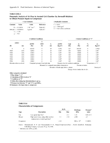
TABLE CDD.3
Pneumatic Analysis of Air Flow to Aerated Grit Chamber (by Bernoulli Relation)
to Obtain Pressure Inputs to Compressor
1 Gas Constants 2 Hydraulic Constants
Constant Value Units Reference f ¼ 0.012
r ¼ 1000 kg=m 3
1
R ¼ 8.314510 J K mol 1 Table B.2
C ¼ 0.61 orifice coefficient
MW(air) ¼ 0.0289641 kg=mol Table B.7
k ¼ 1.395
g ¼ 9.81
3 Ambient Conditions 4 Intake Conditions at ‘‘1’’
T
z(elev)
p(atm) (atm) z 1 r(atm) z 1 rg p 1 T 1 r 1
3
3
(ft) (m) (Pa) (C) (m) (kg=m ) (Pa) (Pa) (C) (kg=m )
0 0 101325 0 10 1.292 127 101325 0 1.2922
5500 1676 82083 0 10 1.047 103 82083 0 1.047
5500 1676 82083 0 10 1.047 103 82083 0 1.047
5500 1676 82083 0 10 1.047 103 82083 0 1.047
5500 1676 82083 0 10 1.047 103 82083 0 1.047
5500 1676 82083 0 10 1.047 103 82083 0 1.047
5500 1676 82083 0 10 1.047 103 82083 0 1.047
Elevation above sea level Computed pressure from Lide data Density of air for ambient conditions Temperature at ‘‘1’’
Measured (or assumed) atmospheric temperature Pressure at intake
Elevation of intake pipe above a datum Density of
Energy of air at intake due to elev.
Other categories calculated
5 Pipe design ‘‘1–2’’
6 Calculation of HGL level at ‘‘2’’
7 Conditions at ‘‘5’’
8 Orifice flow=sizing=Dp determinations to get p 4
9 Pressure loss between ‘‘3’’ and ‘‘4’’ to get HGL 3
10 Summary—for input data to compressor
TABLE D.4
Characteristics of Compressors
p 2 =p 1 a
Discharge Pressure
Type Description Min Max (kPa) (atm)
a
Fan Low speed, high flow <1.1 1–15 0.01–0.15
Blower High speed rotary, using either positive 1.1 <3.0 200 2
a
displacement or centrifugal force
Compressor >3.0 200–n 10 5 2–1000’s
Source: Cheremisinoff, N. P. and Cheremisinoff, P. N., Pumps=Compressors=Fans – Pocket Handbook, Technomic
Publishing Company, Lancaster, PA, p. 78, 1989.
a
McCabe et al. (1993, p. 204).