Page 846 - Fundamentals of Water Treatment Unit Processes : Physical, Chemical, and Biological
P. 846

Appendix D:  Fluid Mechanics—Reviews of Selected Topics                                          801


                                                               converting Equation D.4 through D.31, i.e., multiplying
                                              p L (1–2)
                                                               both sides of Equation D.16 by g, i.e.,
                                               p L (3–4) p L (1–4) Pipe losses
                                                                       p 1   v 2 1        p 2    v 2 2
             ΔP (compressor)                                     z 1 g þ  g þ   g ¼ z 2 g þ  g þ   g þ h L(1 2) g 2
                                                                    1
                                                                          1
                                                                                                    2
                                                                                             2
                                                                                       2
                                                                                 1
                                                                       g     2g           g      2g
                                                   p L (4–5) Orifice
                                                                                                           (D:32)
                         p 3
                                        p 4
                                                               Following through for the three energy terms, given as Equa-
                                               p 5
                                                               tion D.30(a), (b), (c),
                     P
            p 2
              1     2  3  z 3   ρg          4  5                                      p       v 2    v 2
                              L                                    (a) zg ¼ zrg  (b) p ¼ g  (c)  g ¼ r     (D:33)
                                                      Datum                           g       2g      2
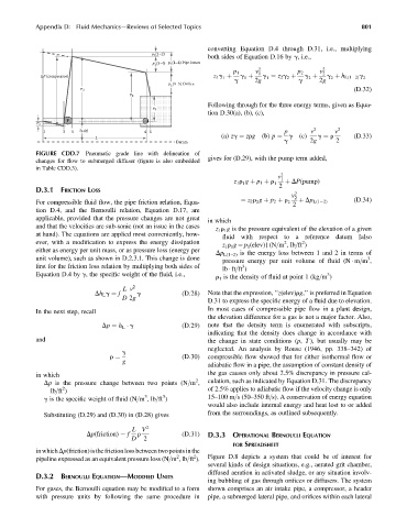
            FIGURE CDD.7   Pneumatic grade line with delineation of
                                                               gives for (D.29), with the pump term added,
            changes for flow to submerged diffuser (figure is also embedded
            in Table CDD.3).
                                                                                    v 2 1
                                                                       z 1 r g þ p 1 þ r 1  þ DP(pump)
                                                                          1
            D.3.1  FRICTION LOSS                                                    2
                                                                                        v 2 2
            For compressible fluid flow, the pipe friction relation, Equa-  ¼ z 2 r g þ p 2 þ r 2  2  þ Dp L(1 2)  (D:34)
                                                                              2
            tion D.4, and the Bernoulli relation, Equation D.17, are
            applicable, provided that the pressure changes are not great
                                                               in which
            and that the velocities are sub-sonic (not an issue in the cases
                                                                  z 1 r 1 g is the pressure equivalent of the elevation of a given
            at hand). The equations are applied most conveniently, how-
                                                                    fluid with respect to a reference datum [also
            ever, with a modification to express the energy dissipation                2    2
                                                                    z 1 r 1 g ¼ p 1 (elev)] (N=m ,lb=ft )
            either as energy per unit mass, or as pressure loss (energy per
                                                                  Dp L(1–2) is the energy loss between 1 and 2 in terms of
            unit volume), such as shown in D.2.3.1. This change is done                                        3
                                                                    pressure energy per unit volume of fluid (N   m=m ,
            first for the friction loss relation by multiplying both sides of  3
                                                                    lb   ft=ft )
            Equation D.4 by g, the specific weight of the fluid, i.e.,                               3
                                                                  r 1 is the density of fluid at point 1 (kg=m )
                                      L v 2
                             Dh L g ¼ f   g            (D:28)  Note that the expression, ‘‘z(elev)rg,’’ is preferred in Equation
                                      D 2g
                                                               D.31 to express the specific energy of a fluid due to elevation.
                                                               In most cases of compressible pipe flow in a plant design,
            In the next step, recall
                                                               the elevation difference for a gas is not a major factor. Also,
                                Dp ¼ h L   g           (D:29)  note that the density term is enumerated with subscripts,
                                                               indicating that the density does change in accordance with
            and                                                the change in state conditions (p, T ), but usually may be
                                                               neglected. An analysis by Rouse (1946, pp. 338–342) of
                                      g
                                                       (D:30)  compressible flow showed that for either isothermal flow or
                                      g
                                  r ¼
                                                               adiabatic flow in a pipe, the assumption of constant density of
            in which                                           the gas causes only about 2.5% discrepancy in pressure cal-
                                                            2
              Dp is the pressure change between two points (N=m ,  culation, such as indicated by Equation D.31. The discrepancy
                    2
                lb=ft )                                        of 2.5% applies to adiabatic flow if the velocity change is only
                                            3
                                                  3
              g is the specific weight of fluid (N=m ,lb=ft )    15–100 m=s (50–350 ft=s). A conservation of energy equation
                                                               would also include internal energy and heat lost to or added
              Substituting (D.29) and (D.30) in (D.28) gives   from the surroundings, as outlined subsequently.
                                        L V  2
                           Dp(friction) ¼ f  r         (D:31)  D.3.3 OPERATIONAL BERNOULLI EQUATION
                                        D   2
                                                                       FOR SPREADSHEET
            inwhichDp(friction)isthefrictionlossbetweentwopointsinthe
                                                      2
                                                           2
            pipeline expressed as an equivalent pressure loss (N=m ,lb=ft ).  Figure D.8 depicts a system that could be of interest for
                                                               several kinds of design situations, e.g., aerated grit chamber,
                                                               diffused aeration in activated sludge, or any situation involv-
            D.3.2  BERNOULLI EQUATION—MODIFIED UNITS
                                                               ing bubbling of gas through orifices or diffusers. The system
            For gases, the Bernoulli equation may be modified to a form  shown comprises an air intake pipe, a compressor, a header
            with pressure units by following the same procedure in  pipe, a submerged lateral pipe, and orifices within each lateral
   841   842   843   844   845   846   847   848   849   850   851