Page 843 - Fundamentals of Water Treatment Unit Processes : Physical, Chemical, and Biological
P. 843

798                                                Appendix D: Fluid Mechanics—Reviews of Selected Topics


                                                                  h L (header)
                                                   HGL(header)   c


                                           b
                             a


                                           g                      HGL(lateral)                d
                            Q(header)                                       h L (lateral)
                                                          Q(orifice)        e h L (orifice) Water surface  h
                                           Q(lateral 2)
                                                                             i Lateral 3  Lateral 4


                                                                            f
                                                      Lateral 1
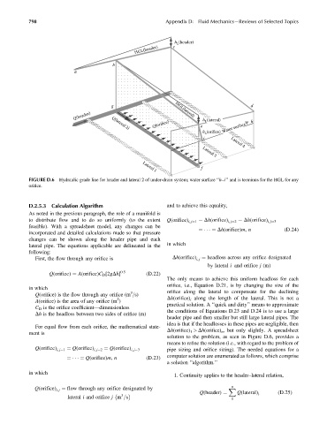
            FIGURE D.6  Hydraulic grade line for header and lateral 2 of under-drain system; water surface ‘‘h–i’’ and is terminus for the HGL for any
            orifice.


            D.2.5.3  Calculation Algorithm                     and to achieve this equality,
            As noted in the previous paragraph, the role of a manifold is
            to distribute flow and to do so uniformly (to the extent  Q(orifice) i, j¼1 ¼ Dh(orifice) i, j¼2 ¼ Dh(orifice) i, j¼3
            feasible). With a spreadsheet model, any changes can be
                                                                           ¼     ¼ Dh(orifice)m, n         (D:24)
            incorporated and detailed calculations made so that pressure
            changes can be shown along the header pipe and each
            lateral pipe. The equations applicable are delineated in the  in which
            following:
              First, the flow through any orifice is               Dh(orifice) i, j ¼ headloss across any orifice designated
                                                                              by lateral i and orifice j (m)
                   Q(orifice) ¼ A(orifice)C D [2gDh] 0:5  (D:22)
                                                               The only means to achieve this uniform headloss for each
                                                               orifice, i.e., Equation D.21, is by changing the size of the
            in which
                                                  3
              Q(orifice) is the flow through any orifice (m =s)   orifice along the lateral to compensate for the declining
                                             2
              A(orifice) is the area of any orifice (m )         Dh(orifice) i along the length of the lateral. This is not a
                                                               practical solution. A ‘‘quick and dirty’’ means to approximate
              C D is the orifice coefficient—dimensionless
                                                               the conditions of Equations D.23 and D.24 is to use a large
              Dh is the headloss between two sides of orifice (m)
                                                               header pipe and then smaller but still large lateral pipes. The
                                                               idea is that if the headlosses in these pipes are negligible, then
              For equal flow from each orifice, the mathematical state-
                                                               Dh(orifice) 1 > Dh(orifice) n , but only slightly. A spreadsheet
            ment is
                                                               solution to the problem, as seen in Figure D.6, provides a
                                                               means to refine the solution (i.e., with regard to the problem of
              Q(orifice) i, j¼1  ¼ Q(orifice) i, j¼2  ¼ Q(orifice) i, j¼3  pipe sizing and orifice sizing). The needed equations for a
                                                               computer solution are enumerated as follows, which comprise
                          ¼     ¼ Q(orifice)m, n       (D:23)
                                                               a solution ‘‘algorithm.’’
            in which
                                                                  1. Continuity applies to the header–lateral relation,
                                                                                       n
              Q(orifice) ¼ flow through any orifice designated by                     X
                      i, j
                                                                                         Q(lateral) i   (D:25)
                                               3                           Q(header) ¼
                          lateral i and orifice j m =s                                 1
   838   839   840   841   842   843   844   845   846   847   848