
Page 842 - Fundamentals of Water Treatment Unit Processes : Physical, Chemical, and Biological
P. 842
Appendix D: Fluid Mechanics—Reviews of Selected Topics 797
D.2.4 PUMP POWER the header pipe and then to each orifice. The ideal would be
that Q(orifice) (1,1) Q(orifice) (n,n) . A means to distribute the
The power supplied to the fluid is
flow approximately uniformly is to oversize each manifold
pipe such that the friction headloss is little in the header pipe,
P(fluid) ¼ QgDH(pump) (D:19)
ensuring Dh is small between any two node points of a
manifold.
The power required by the shaft to the pump is
Examples of manifold design include a filtration under-
drain=backwash system in which uniform flow distribution is
Qg DH(pump)
(D:20) essential, distribution of air from a pipe gallery header to
h(pump) laterals in aeration basins and then further distribution from
P(shaft) ¼
the laterals through diffusers. In any pipe gallery in either a
in which water treatment plant or in a wastewater treatment plant,
P is the power supplied to fluid (Nm=sor W) various pipes are evident as flows must be distributed to or
P(shaft) is the power supplied to shaft (W) taken from the adjacent basins. A manifold pipe (or header
h(pump) is the pump efficiency defined as ratio P(fluid)= pipe) is the means to distribute such flows.
P(shaft)
D.2.5.2 Effect of Headloss on Manifold Flows
The power required for the motor is another issue and is
defined as In general, the purpose of a manifold is to distribute flows
uniformly to each lateral and then to some kind of outlets such
as orifices or diffusers (also with uniform flow to each). As
P(shaft)
(D:21) stated in the foregoing paragraph, Figure D.5a and b illustrate
h(motor) ¼
VA
this principle.
Figure D.6 is but a perspective drawing of a manifold
in which
system, e.g., as illustrated in Figure D.5. It depicts a system
P(motor) is the power from electric energy supplied to
with a header pipe showing only four laterals, with orifices
motor (watts)
spaced along the length of each lateral. Lateral 2 (i ¼ 2) is
V is the voltage across motor (volts)
highlighted for illustration. The hydraulic grade line (HGL)
A is the amperage of motor (amperes)
for the header pipe, abc, is shown with friction headloss
indicated to the end of the pipe. The HGL for lateral 2 is
D.2.5 MANIFOLDS shown from b with slope in the direction of the flow. Finally,
the HGL must end at the water surface and the HGL drops
A problem that appears frequently in plant design is manifold
precipitously at e to i, the water surface in the filter bed (also
sizing. A manifold is a means to distribute a fluid to other
the terminus of the HGL). The HGL for the header, as
pipes or through openings within a given pipe. A pipe that
sketched, shows a straight line, i.e., the slope is uniform. In
serves as a manifold to other pipes, called ‘‘laterals,’’ may be
reality, the slope changes at each lateral as the header loses
called a ‘‘header’’ pipe. 2
flow, since the slope is h L =L ¼ ( f=D)(v =2g) and v ¼ Q=A. The
same is true for the HGL for each lateral; the HGL slope is
D.2.5.1 Basics of Manifold Hydraulics reduced incrementally at each orifice (or diffuser). This means
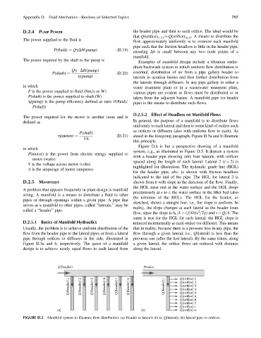
Usually, the problem is to achieve uniform distribution of the that in reality, because there is a pressure loss in any pipe, the
flow from the header pipe to the lateral pipes or from a lateral flow through a given lateral, i.e., Q(lateral) is less than the
pipe through orifices or diffusers in the side, illustrated in previous one (after the first lateral). By the same token, along
Figure D.5a and b, respectively. The quest of a manifold a given lateral, the orifice flows are reduced with distance
design is to achieve nearly equal flows to each lateral from along the lateral.
Q(header) Header
Q(header) 1 Q(header) 2 Q(header) 3 Q(header) 4 Q(header) i Q(header) n Q(header) i Q(orifice) 1
Q(orifice) 2
Q(orifice) 3
Q(orifice) 4
Q(orifice) 5
Q(orifice) 5
Q(orifice) 6
Q(orifice) 7
Q(orifice) i
(a) (b) Q(orifice) n
FIGURE D.5 Manifold system to illustrate flow distribution. (a) Header to laterals fixto Q(lateral); (b) lateral pipe to orifices.