
Page 838 - Fundamentals of Water Treatment Unit Processes : Physical, Chemical, and Biological
P. 838
Appendix D: Fluid Mechanics—Reviews of Selected Topics 793
Relative roughness, e/D
0.10
0.05
Laminar
0.01
f
0.001
0.0001
0.00001
Smooth
0.01
10 3 10 4 10 5 10 6 10 7 10 8
R
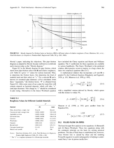
FIGURE D.2 Moody diagram f or friction factor as function of R for different values of relative roughness. (From Albertson, M.L. et al.,
Fluid Mechanics for Engineers, Prentice-Hall, Englewood Cliffs, NJ, p. 269, 1960).
Moody’s paper, indicating his objections. The pipe friction have included the Chezy equation and Hazen and Williams
diagram as adapted by Moody became well known worldwide equation. The C coefficients for these equations are available
and is known today as the ‘‘Moody diagram.’’ in various handbooks. The Darcy–Weisbach is the preferred
Figure D.2 is the Moody diagram for pipe friction, which relation, albeit practice seems to employ, to a large extent, the
shows how pipe friction varies with R and relative roughness, latter two empirical equations (Box D.1).
e=D. Table D.1 gives ‘‘e’’ values for various materials. Thus, A mathematical relation that incorporates e=D and R to
to determine the friction factor, first determine the kind of predict f is the Colebrook function (Daugherty and Ingersoll,
material used and then select an ‘‘e.’’ For a selected R and a 1954, p. 181; Munson et al. 1998, p. 494),
known (or assumed) pipe diameter, e=D is calculated. From
these ‘‘arguments,’’ the friction factor, ‘‘f’’ is obtained from
1 e=D 2:51
Figure D.2. After some years of use a pipe for water flow will p ffiffi ¼ 2 log þ p ffiffi (D:5)
3:7
contain mineral or bacterial deposits, which will alter ‘‘e’’ f R f
(and pipe diameter). This change in ‘‘e’’ should be considered
in pipe sizing. Alternatives to the Darcy–Weisbach equation with a simplified version derived by Moody, which agrees
with the former to within 5%,
6
TABLE D.1 e 10
f ¼ 0:0055 1 þ 20, 000 þ (D:6)
Roughness Values for Different Conduit Materials D R
a
«
Munson et al. (1998, p. 541) gave another form for
Material (ft) (mm)
Equation D.6,
Glass, drawn brass, copper, lead Smooth Smooth
Commercial steel, wrought iron 0.0001–0.0003 0.03–0.09
1:325
Asphalted cast iron 0.0002–0.0006 0.06–0.18 (D:7)
2
f ¼
0:9
Galvanized iron 0.0002–0.0008 0.06–0.24 ln e=3:7DÞ þ 5:74=R
ð
Cast iron 0.0004–0.002 0.12–0.61
Wood stave 0.0006–0.003 0.18–0.91
D.2 FLUID FLOW IN PIPES
Concrete 0.001–0.01 0.30–3.0
Riveted steel 0.003–0.03 0.91–9.1
The basis for pipe flow analysis is two equations: (1) Bernoulli
Corrugated metal pipe 0.1–0.2 30–61
and (2) Darcy–Weisbach. These two equations along with
Blasted rock tunnels 1.0 300
the continuity principle are the basis for solving practical
problems. The idea of fluid shear is established first, however,
Source: Data from Albertson, M. L. et al., Fluid Mechanics for Engineers,
Prentice-Hall, Englewood Cliffs, NY, 1960, p. 268. since friction loss is caused by shear and the resulting
a Poiseuille equation is useful subsequently in helping to under-
The ‘‘e’’ is a roughness parameter for different pipe materials.
stand Darcy’s law in porous media flow.