
Page 847 - Fundamentals of Water Treatment Unit Processes : Physical, Chemical, and Biological
P. 847
802 Appendix D: Fluid Mechanics—Reviews of Selected Topics
1000 mL ΔV(air) Ball valve d
Graduated Ball valve b Ball valve c
cylinder
Throttling valve a Plastic tank
Bucket Rotometer
of water
Bubbles
ΔH
Q(diffuser)
P Diffuser
Rotometer calibration Diffuser set-up for coefficient
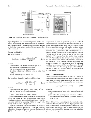
FIGURE D.8 Laboratory set-up for determination of diffuser coefficient.
pipe. The problem is to determine the pressure that the com- displacement of water. A graduated cylinder is filled with
pressor must develop. The design may involve ‘‘scenarios’’ air-saturated water and inverted in the volume of water. An air
and so a spreadsheet is most useful. Several steps are involved tube is placed in the cylinder and at time t ¼ 0, the ball valve b
in developing a spreadsheet solution. The spreadsheet algo- is opened, and the rotometer ball reading is taken. After a
rithm is outlined. reasonable displacement, the volume V is measured and t is
recorded, with Q(air) ¼ DV=Dt. The throttling valve ‘‘a’’ is
D.3.3.1 Orifice Flow changed so that Q(air) is different and the process is repeated.
The orifice equation is To determine K, the ball valves ‘‘b’’ and ‘‘d’’ are closed and
ball valve ‘‘c’’ is opened. For a given setting of the throttling
0:5
2Dp(orifice) valve ‘‘a,’’ the air flow is then measured by the rotometer and
Q(orifice) ¼ A(orifice)C (D:35) the headloss across the diffuser, Dh(diffuser), is measured at
r(gas)
the same time. The air temperature should be measured also
in which probably near valve ‘‘c.’’ The throttling valve ‘‘a’’ is adjusted
3
Q(orifice) is the flow through a single orifice (m =s) and the process is repeated. After enough points are obtained,
2
A(orifice) is the area of a single orifice (m ) K can be determined. The density r(air) is calculated by the
gas law, i.e., PV ¼ nRT, to give r(air) ¼ P MW(air)=RT, with
C is the orifice coefficient (dimensionless)
P ¼ Dh(diffuser) g w þ p(atm).
Dp(orifice) is the pressure difference across an orifice plate
(Pa)
3
r is the density of gas (kg gas=m gas) D.3.3.2 Submerged Flow
When an air bubble emerges from an orifice or a diffuser or
The same form of equation applies to a diffuser, i.e., appears spontaneously by gas precipitation, the absolute pres-
sure inside the bubble equals the pressure due to the water
0:5
Dp(diffuser) depth plus the atmospheric pressure on the water surface, i.e.,
Q(diffuser) ¼ K (D:36)
r(gas)
p 5 ¼ g D(water) þ p(atm) (D:37)
w
in which
3
Q(diffuser) is the flow through a single diffuser (m =s) in which
2
K is the ‘‘lumped’’ coefficient for diffuser (m ) D(water) is the depth of orifice below water surface in tank
(m)
D.3.3.1.1 Determination of K for a Diffuser p(atm) is the atmospheric pressure under local conditions
Diffusers are proprietary with K being unique for a particular dependent on elevation, or more accurately, barometric
design. The K must be either supplied by the manufacturer pressure (Pa)
(usually not available) or determined by a laboratory test. The
laboratory test involves measuring Q(diffuser) v. Dp=r with Figure D.8 shows the pneumatic grade line terminating at the
enough points to define a straight line. surface of the water, which is the case if gage pressure is the
Figure D.8 shows the experimental set-up for the deter- basis for the diagram. If absolute pressure is used as the basis,
mination of K. To measure Q(diffuser), a rotometer should be all points of the pneumatic grade line have added one atmos-
selected for the range of air flow expected. Calibration of phere of local pressure. Note that the pressure term in the ideal
Q(air) v. ball position reading may be done by volumetric gas law is absolute pressure.