
Page 147 - Gas Purification 5E
P. 147
136 Gas Purification
I
I
I \
I \
I \
I I
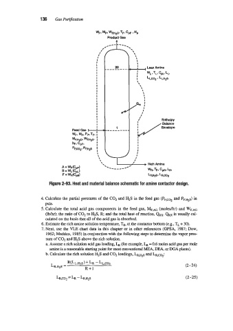
! LeanAmine
WL I TL, C~L,
L,,
! LLC02’LLHzS
\
\
\
I \
I \
I
I
2.. ;
I
I
/
I
I
Enthalpy
I
Balance
Envelope
I
I
I
I
I
I
I
I
I
Figure 2-93. Heat and material balance schematic for amine contactor design.
4. Calculate the partial pressures of the C02 and H2S in the feed gas (PF,coz and PF.H2~)
in
psia.
5. Calculate the total acid gas components in the feed gas, MF,AG (moleshr) and WF.*~
(Iblhr); the ratio of C02 to H2S, R; and the total heat of reaction, QRx. QRx is usually cal-
culated on the basis that all of the acid gas is absorbed.
6. Estimate the rich amine solution temperature, TR, at the contactor bottom (e.g.? TL + 30).
7. Next, use the VLE chart data in this chapter or in other references (GPSA, 1987; Dow,
1962; Maddox, 1985) in conjunction with the following steps to determine the vapor pres-
sure of C02 and HIS above the rich solution.
a. Assume a rich solution acid gas loading, r, (for example, r, = 0.6 moles acid gas per mole
amine is a reasonable skuting point for most conventional MEA, DEA, or JXA plants).
b. Calculate the rich solution H2S and C02 loadings, LR,H~S and LR,c%:
(2 - 24)
LR,CO-, = LR - LR,H2S (2-25)