
Page 270 - gas transport in porous media
P. 270
Chapter 14: Experimental Determination of Transport Parameters
267
and has to be solved together with the appropriate boundary and initial conditions (see,
Arnošt and Schneider, 1995), for example, by the finite difference method (Ehrhardt
et al., 1988).
If, instead of Eq. (14.50), the simple Fick’s law is used, the resulting set of lin-
ear differential mass balances can be solved by Laplace transformation (see e.g.,
U
Burghardt and Smith, 1979). For high carrier-gas flow-rates in both chambers, F ,
L
F , and impulse perturbation by tracer gas, T, in the upper cell compartment, the first
absolute moment of the tracer response in the lower chamber is given by
2
L ε V U V L
p
¯ µ = + + (14.51)
1 U L
6D TC F F
The effective diffusion coefficient D TC (see Eq. (14.30)) contains the trans-
port parameters ψ and r ψ. Moment expressions for more general situations are
summarized in (Arnošt and Schneider, 1994).
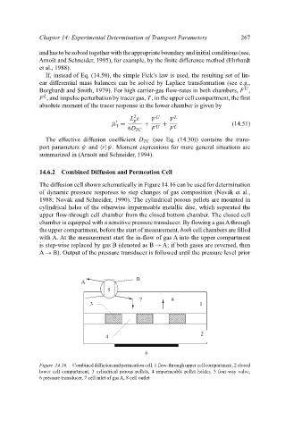
14.6.2 Combined Diffusion and Permeation Cell
The diffusion cell shown schematically in Figure 14.16 can be used for determination
of dynamic pressure responses to step changes of gas composition (Novák et al.,
1988; Novák and Schneider, 1990). The cylindrical porous pellets are mounted in
cylindrical holes of the otherwise impermeable metallic disc, which separated the
upper flow-through cell chamber from the closed bottom chamber. The closed cell
chamber is equipped with a sensitive pressure transducer. By flowing a gasAthrough
the upper compartment, before the start of measurement, both cell chambers are filled
with A. At the measurement start the in-flow of gas A into the upper compartment
is step-wise replaced by gas B (denoted as B → A; if both gases are reversed, then
A → B). Output of the pressure transducer is followed until the pressure level prior
B
A
5
7 8
3 1
2
4
6
Figure 14.16. Combined diffusion and permeation cell. 1 flow-through upper cell compartment, 2 closed
lower cell compartment, 3 cylindrical porous pellets, 4 impermeable pellet holder, 5 four-way valve,
6 pressure transducer, 7 cell inlet of gas A, 8 cell outlet