
Page 268 - gas transport in porous media
P. 268
Chapter 14: Experimental Determination of Transport Parameters
Full 265
100 100
solution
Simplified
p (kPa) 50 solution 50 p (kPa)
0 0
0 0 500 1000
t (s)
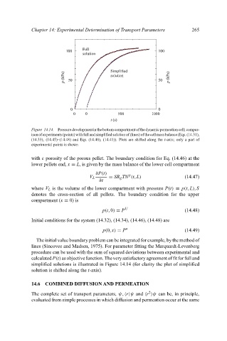
Figure 14.14. Pressuredevelopmentinthebottomcompartmentofthedynamicpermeationcell; compar-
isonofexperiments(points)withfullandsimplifiedsolutionof(lines)ofthecellmassbalance(Eqs.(14.31),
(14.33), (14.45)–(14.48) and Eqs. (14.40), (14.41)). Plots are shifted along the t-axis; only a part of
experimental points is shown
with ε porosity of the porous pellet. The boundary condition for Eq. (14.46) at the
lower pellets end, x = L, is given by the mass balance of the lower cell compartment
∂P(t) p
V L = SR g TN (t, L) (14.47)
∂t
where V L is the volume of the lower compartment with pressure P(t) ≡ p(t, L), S
denotes the cross-section of all pellets. The boundary condition for the upper
compartment (x = 0) is
p(t,0) = P U (14.48)
Initial conditions for the system (14.32), (14.34), (14.46), (14.48) are
p(0, x) = P o (14.49)
The initial value boundary problem can be integrated for example, by the method of
lines (Sincovee and Madsen, 1975). For parameter fitting the Marquardt-Levenberg
procedure can be used with the sum of squared deviations between experimental and
calculatedP(t)asobjectivefunction. Theverysatisfactoryagreementoffitforfulland
simplified solutions is illustrated in Figure 14.14 (for clarity the plot of simplified
solution is shifted along the t-axis).
14.6 COMBINED DIFFUSION AND PERMEATION
2
The complete set of transport parameters, ψ, r ψ and r ψ can be, in principle,
evaluated from simple processes in which diffusion and permeation occur at the same