
Page 297 - gas transport in porous media
P. 297
Chapter 17: Subsurface Flow Measurements
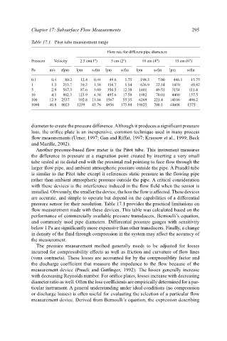
Table 17.1. Pitot tube measurement range
Flow rate for different pipe diameters 295
Pressure Velocity 2.5 cm(1") 5 cm (2") 10 cm (4") 15 cm (6")
Pa m/s sfpm lpm scfm lpm scfm lpm scfm lpm scfm
0.1 0.4 80.2 12.4 0.44 49.6 1.75 198.3 7.00 446.1 15.75
1 1.3 253.7 39.2 1.38 156.7 5.54 626.9 22.14 1410 49.82
5 2.9 567.3 87.6 3.09 350.5 12.38 1401 49.51 3154 111.4
10 4.1 802.3 123.9 4.38 495.6 17.50 1982 70.01 4460 157.5
100 12.9 2537 392.8 13.84 1567 55.35 6269 221.4 14106 498.2
1000 40.8 8023 1239 43.76 4956 175.04 19825 700.1 44608 1575
diameter to create the pressure difference. Although it produces a significant pressure
loss, the orifice plate is an inexpensive, common technique used in many process
flow measurements (Urner, 1997; Gan and Riffat, 1997; Krassow et al., 1999; Beck
and Mazille, 2002).
Another pressure-based flow meter is the Pitot tube. This instrument measures
the difference in pressure at a stagnation point created by inserting a very small
tube sealed at its distal end with the proximal end pointing to face flow through the
larger flow pipe, and ambient atmospheric pressure outside the pipe. A Prandtl tube
is similar to the Pitot tube except it references static pressure in the flowing pipe
rather than ambient atmospheric pressure outside the pipe. A critical consideration
with these devices is the interference induced in the flow field when the sensor is
installed. Obviously, the smaller the device, the less the flow is affected. These devices
are accurate, and simple to operate but depend on the capabilities of a differential
pressure sensor for their resolution. Table 17.1 provides the practical limitations on
flow measurement made with these devices. This table was calculated based on the
performance of commercially available pressure transducers, Bernoulli’s equation,
and commonly used pipe diameters. Differential pressure gauges with sensitivity
below 1 Pa are significantly more expensive than other transducers. Finally, a change
in density of the fluid through compression in the system may affect the accuracy of
the measurement.
The pressure measurement method generally needs to be adjusted for losses
incurred for compressibility effects as well as friction and curvature of flow lines
(vena contracta). These losses are accounted for by the compressiblity factor and
the discharge coefficient that measure the impedance to the flow because of the
measurement device (Pnueli and Gutfinger, 1992). The losses generally increase
with decreasing Reynolds number. For orifice plates, losses increase with decreasing
diameter ratio as well. Often the loss coefficients are empirically determined for a par-
ticular instrument. A general understanding under ideal conditions (no compression
or discharge losses) is often useful for evaluating the selection of a particular flow
measurement device. Derived from Bernoulli’s equation, the expression describing