
Page 92 - Geochemical Remote Sensing of The Sub-Surface
P. 92
Geoelectrochemistry and stream dispersion 69
16
, 2,,..~ i
:J. !
7 ,
A Mt M2 M3 M4 Ms M6 M7 M8 B
v
cathodic t egion anodic region
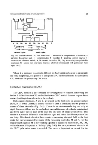
Fig. 2-45. Scheme of the CLPC field installation: 1- transducer of compensation; 2- ammeter; 3-
galvanic decoupling unit; 4- potentiometer; 5- recorder; 6- electrical current source; 7-
measurement channels switch; A, B- current electrodes; Mi,...M8 -measuring non-polarisable
electrodes; N- remote non-polarisable reference electrode (reproduced with permission from
Ryss, 1983).
Where it is necessary to correlate different ore-body cross-sections or to investigate
ore-body morphology, it is possible to use special CPC field installations, the correlation
CPC mode and the prospecting CPC mode.
Contactless polarisation (CLPC)
The CLPC method is also intended for investigations of electron-conducting ore
bodies. It differs from the CPC method in that the CLPC method does not require direct
contact (earthing) of one electrode in the ore body.
Both current electrodes, A and B, are placed in the host rocks on ground surface
(Ryss, 1973, 1983). Current, as a linear function of time, is introduced into the ground by
means of these electrodes (Fig. 2-45). If there is an electron-conducting ore body at
depth this current flows into the ore body at one end (the zone of cathodic polarisation)
and flows out of the ore body at the other end (the zone of anodic polarisation). This
results in a potential difference with different signs and values in different parts of the
ore body. This double electrical layer creates a secondary electrical field in the host
rocks that can be measured by means of the measuring electrodes, M and N. For this
measurement electrode M is moved along a profile to successive positions M~, M2, ..Mn
whilst electrode N is placed at "infinity" (Fig. 2-45). For each position of electrode M
the CLPC polarisation curve is recorded. This curve is dependent on current I in the