
Page 93 - Geochemical Remote Sensing of The Sub-Surface
P. 93
70 O.F. Putikov and B. Wen
Ilim I a
lliml C,,i | ....
e
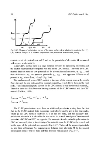
Fig. 2-46. Shapes of polarisation curves of the same surface of an electronic conductor for: (1)
CPC method: and (2) CLPC method (reproduced with permission from Putikov, 1993).
current circuit of electrodes A and B and on the potentials of electrodes M, measured
with respect to electrode N.
In the CLPC method there is a large distance between the measuring electrodes and
the double electrical layer compared with that in the CPC method. Therefore the CLPC
method does not measure true potentials of the electrochemical reactions, q)~, q~2, ... and
their differences Aq~, but apparent potentials %~, qga2, ...and apparent differences of
potentials A%, where [A% ]< I Aq, I (Fig. 2-46).
The total current I in the CLPC method is the sum of the internal current I~n, which
flows through the ore body, and the external current Iext, which flows through the host
rocks. The corresponding total current for the CPC method is only the internal current I~,.
Therefore there is a link between limiting currents of the CLPC method and the CPC
method (Putikov, 1993),
IlimCLPC = Ilimi,, + Iext -- IlimCeC + I,..,r
IlimCLP C > IlimCPC
The CLPC polarisation curves have an additional peculiarity arising from the fact
that in the CLPC method both measuring electrodes M and N are in the host rocks,
whilst in the CPC method electrode M is in the ore body, and the auxiliary non-
polarisable electrode N is placed in the host rocks. As a result the signs of the measured
potentials of CLPC and CPC are opposite. For example, if under cathodic polarisation in
CPC we have q)<0, then in the vicinity of the cathodic zone for CLPC we have q)>0 and
so the signs of the potentials are opposite (Fig. 2-47). Values of the apparent potentials
qh~ and their differences A(Da depend upon distance from electrode M~ to the nearest
polarisation zone of the ore body and they decrease with distance (Fig. 2-47).