
Page 123 - Geothermal Energy Renewable Energy and The Environment
P. 123
Exploring for Geothermal Systems 109
Source Receiver
R 1
R 2
Z 0
Z 1
Z 2
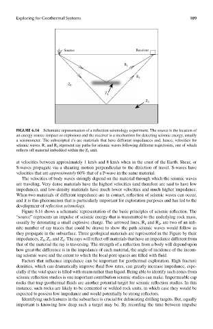
FIGUre 6.14 Schematic representation of a reflection seismology experiment. The source is the location of
an energy source (impact or explosion) and the receiver is a mechanism for detecting seismic energy, usually
a seismometer. The subscripted z’s are materials that have different impedances and, hence, velocities for
seismic waves. R 1 and R 2 represent ray paths for seismic waves following different trajectories, one of which
reflects off material imbedded within the Z 0 unit.
at velocities between approximately 1 km/s and 8 km/s when in the crust of the Earth. Shear, or
S-waves propagate via a shearing motion perpendicular to the direction of travel. S-waves have
velocities that are approximately 60% that of a P-wave in the same material.
The velocities of body waves strongly depend on the material through which the seismic waves
are traveling. Very dense materials have the highest velocities (and therefore are said to have low
impedance), and low-density materials have much lower velocities and much higher impedance.
When two materials of different impedance are in contact, reflection of seismic waves can occur,
and it is this phenomenon that is particularly important for exploration purposes and has led to the
development of reflection seismology.
Figure 6.14 shows a schematic representation of the basic principles of seismic reflection. The
“source” represents an impulse of seismic energy that is transmitted to the underlying rock mass,
usually by detonating a small explosive charge. The arrowed lines, R and R , are two of an infi-
2
1
nite number of ray traces that could be drawn to show the path seismic waves would follow as
they propagate in the subsurface. Three geological materials are represented in the Figure by their
impedances, Z , Z , and Z . The rays will reflect off materials that have an impedance different from
2
1
0
that of the material the ray is traversing. The strength of a reflection from a body will depend upon
how great the difference is in the impedance of each material, the angle of incidence of the incom-
ing seismic wave and the extent to which the local pore spaces are filled with fluid.
Factors that influence impedance can be important for geothermal exploration. High fracture
densities, which can dramatically improve fluid flow rates, can greatly increase impedance, espe-
cially if the void space is filled with steam rather than liquid. Being able to identify such zones from
seismic reflection studies is one important contribution seismic studies can make. Impermeable cap
rocks that trap geothermal fluids are another potential target for seismic reflection studies. In this
instance, such rocks are likely to be cemented or welded rock units, in which case they would be
expected to possess low impedance and would potentially be strong reflectors.
Identifying such features in the subsurface is crucial for delineating drilling targets. But, equally
important is knowing how deep such a target may be. By recording the time between impulse