
Page 159 - Geothermal Energy Renewable Energy and The Environment
P. 159
Drilling 145
T (°C)
600 400 300 200 100
1000
Kakkonda
100 Imperial valley
K 1
Pressure (MPa) 10 Na 1 K 2 Na 2
1 H O
2
L V
0.1
1.0 2.0 3.0
1000/T (°C)
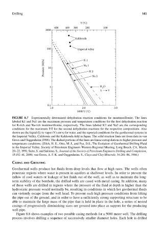
FIGUre 8.7 Experimentally determined dehydration reaction conditions for montmorillonite. The lines
labeled K1 and Na1 are the maximum pressure and temperature conditions for the first dehydration reaction
for K-rich and Na-rich montmorillonite, respectively. The lines labeled K2 and Na2 are the corresponding
conditions for the maximum P-T for the second dehydration reactions for the respective compositions. Also
shown are the liquid (L) to vapor (V) curve for water, and the reported conditions for the geothermal systems in
the Imperial Valley, California and the Kakkonda field in Japan. The solid reaction lines are from data in van
Groos and Guggenheim (1986). The dashed portions of the lines are linear extrapolations to higher pressure and
temperature conditions. (Zilch, H. E., Otto, M. J., and Pye, D.S., The Evolution of Geothermal Drilling Fluid
in the Imperial Valley. Society of Petroleum Engineers Western Regional Meeting, Long Beach, CA, March
20–22, 1991; Saito, S. and Sakuma. S., Journal of the Society of Petroleum Engineers Drilling and Completion,
15:152–61, 2000; van Groos, A. F. K. and Guggenheim. S., Clays and Clay Minerals, 34:281–86, 1986.)
casinG and GrouTinG
Geothermal wells produce hot fluids from deep levels that flow at high rates. The wells often
penetrate regions where water is present in aquifers at shallower levels. In order to prevent the
inflow of cool waters or leakage of hot fluids out of the well, as well as to maintain the long-
term stability of the borehole, the drilled wells are cased with metal casing. In addition, many
of these wells are drilled in regions where the pressure of the fluid at depth is higher than the
hydrostatic pressure would normally be, resulting in conditions in which hot geothermal fluids
can violently escape from the well head. To prevent such high pressure conditions from lifting
the pipe out of the ground, and in order to have a sufficiently strong supporting structure to be
able to maintain the large mass of the pipe that is held in place in the hole, a series of nested
casings of progressively diminishing sizes are grouted into place as support for the producing
well pipe.
Figure 8.8 shows examples of two possible casing methods for a 5000 meter well. The drilling
process involves drilling a sequence of successively smaller diameter holes. Each hole is drilled