
Page 160 - Geothermal Energy Renewable Energy and The Environment
P. 160
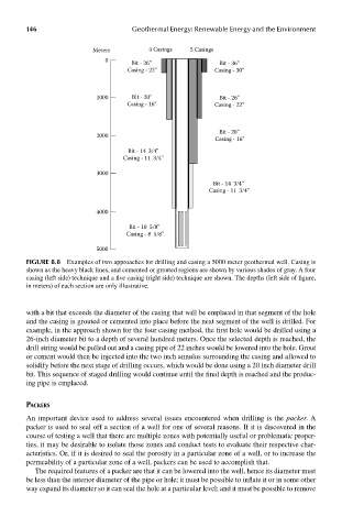
146                          Geothermal Energy: Renewable Energy and the Environment


                              Meters         4 Casings   5 Casings
                                 0       Bit - 26''              Bit - 36''
                                       Casing - 22''           Casing - 30''


                               1000      Bit - 20''              Bit - 26''
                                       Casing - 16''           Casing - 22''


                                                                 Bit - 20''
                               2000
                                                               Casing - 16''
                                        Bit - 14  3/4''
                                      Casing - 11  3/4''

                               3000
                                                               Bit - 14  3/4''
                                                              Casing - 11  3/4''


                               4000
                                        Bit - 10  5/8''
                                       Casing - 8  5/8''

                               5000
            FIGUre 8.8  Examples of two approaches for drilling and casing a 5000 meter geothermal well. Casing is
            shown as the heavy black lines, and cemented or grouted regions are shown by various shades of gray. A four
            casing (left side) technique and a five casing (right side) technique are shown. The depths (left side of figure,
            in meters) of each section are only illustrative.


            with a bit that exceeds the diameter of the casing that will be emplaced in that segment of the hole
            and the casing is grouted or cemented into place before the next segment of the well is drilled. For
            example, in the approach shown for the four casing method, the first hole would be drilled using a
            26-inch diameter bit to a depth of several hundred meters. Once the selected depth is reached, the
            drill string would be pulled out and a casing pipe of 22 inches would be lowered into the hole. Grout
            or cement would then be injected into the two inch annulus surrounding the casing and allowed to
            solidify before the next stage of drilling occurs, which would be done using a 20 inch diameter drill
            bit. This sequence of staged drilling would continue until the final depth is reached and the produc-
            ing pipe is emplaced.


            pacKers
            An important device used to address several issues encountered when drilling is the packer. A
            packer is used to seal off a section of a well for one of several reasons. If it is discovered in the
            course of testing a well that there are multiple zones with potentially useful or problematic proper-
            ties, it may be desirable to isolate those zones and conduct tests to evaluate their respective char-
            acteristics. Or, if it is desired to seal the porosity in a particular zone of a well, or to increase the
            permeability of a particular zone of a well, packers can be used to accomplish that.
              The required features of a packer are that it can be lowered into the well, hence its diameter must
            be less than the interior diameter of the pipe or hole; it must be possible to inflate it or in some other
            way expand its diameter so it can seal the hole at a particular level; and it must be possible to remove