
Page 180 - Geothermal Energy Renewable Energy and The Environment
P. 180
166 Geothermal Energy: Renewable Energy and the Environment
which assures sufficient velocity for efficient separation. The liquid droplets collect on the interior
walls of the separator and flow to a collection basin at the bottom of the collector, from which an
outlet pipe allows drainage to a collection facility. Dry vapor exits through a high standing pipe in
the interior of the vessel and passes to the steam inlet of the turbine.
From this point on, the performance of the turbine-generator system is the same as described for
the dry-steam resource. The only difference overall remains the energy available per unit of mass
of fluid that is extracted from the well, as noted above.
dual-flash sysTems
An innovation that allowed more complete extraction of energy from the geothermal fluids was the
development of the dual-flash power plant. Although such plants are more complex, they can be
economically justified in many instances because the increase cost of development, operation, and
maintenance is more than offset by the income provided by the increased power production.
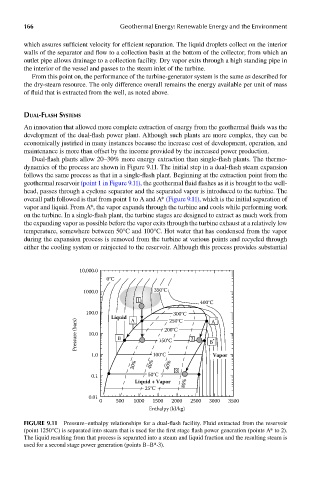
Dual-flash plants allow 20–30% more energy extraction than single-flash plants. The thermo-
dynamics of the process are shown in Figure 9.11. The initial step in a dual-flash steam expansion
follows the same process as that in a single-flash plant. Beginning at the extraction point from the
geothermal reservoir (point 1 in Figure 9.11), the geothermal fluid flashes as it is brought to the well-
head, passes through a cyclone separator and the separated vapor is introduced to the turbine. The
overall path followed is that from point 1 to A and A* (Figure 9.11), which is the initial separation of
vapor and liquid. From A*, the vapor expands through the turbine and cools while performing work
on the turbine. In a single-flash plant, the turbine stages are designed to extract as much work from
the expanding vapor as possible before the vapor exits through the turbine exhaust at a relatively low
temperature, somewhere between 50°C and 100°C. Hot water that has condensed from the vapor
during the expansion process is removed from the turbine at various points and recycled through
either the cooling system or reinjected to the reservoir. Although this process provides substantial
10,000.0
0°C
1000.0 350°C
1 400°C
100.0 300°C
Liquid A 250°C A *
Pressure (bars) 10.0 B 150°C 2 B *
200°C
1.0 100°C Vapor
20% 40% 60%
0.1 50°C 3
Liquid + Vapor 80%
25°C
0.01
0 500 1000 1500 2000 2500 3000 3500
Enthalpy (kJ/kg)
FIGUre 9.11 Pressure–enthalpy relationships for a dual-flash facility. Fluid extracted from the reservoir
(point 1250°C) is separated into steam that is used for the first stage flash power generation (points A* to 2).
The liquid resulting from that process is separated into a steam and liquid fraction and the resulting steam is
used for a second stage power generation (points B–B*-3).