
Page 82 - Geothermal Energy Renewable Energy and The Environment
P. 82
66 Geothermal Energy: Renewable Energy and the Environment
Farrar, C. D., M. L. Sorey, E. Roeloffs, D. L. Galloway, J. F. Howle, and R. Jacobson. 2003. “Inferences on
the Hydrothermal System Beneath the Resurgent Dome in Long Valley Caldera, East-Central California,
USA, From Recent Pumping Tests and Geochemical Sampling.” Journal of Volcanology and Geothermal
Research 127:305–28.
Hill, D. P., W. L. Ellsworth, M. J. S. Johnston, J. O. Langbein, D. H. Oppenheimer, A. M. Pitt, P. A. Reasenberg,
M. L. Sorey, and S. R. McNutt. 1990. “The 1989 Earthquake Swarm Beneath Mammoth Mountain,
California: An Initial Look at the 4 May Through 30 September Activity.” Bulletin of the Seismological
Society of America 80:325–39.
Kosugi, K., and J. W. Hopmans. 1998. “Scaling Water Retention Curves for Soils with Lognormal Pore-Size
Distribution.” Soil Science Society of America Journal 62:1496–1505.
Kozeny, J. 1927. “Über kapillare Leitung des Wassers im Boden. Sitzungsber.” Akademii Wissenschaft Wien
136:271–306.
Lee, C. H., and I. W. Farmer. 1990. “A Simple Method of Estimating Rock Mass Porosity and Permeability.”
International Journal of Mining and Geological Engineering 8:57–65.
Lucia, F. J. 1995. “Rock-Fabric/Petrophysical Classification of Carbonate Pore Space for Reservoir
Characterization.” American Association of Petroleum Geologists 79:1275–1300.
Manning, C. E., and S. E. Ingebritsen. 1999. “Permeability of the Continental Crust: Implications of Geothermal
Data and Metamorphic Systems.” Reviews of Geophysics 37:127–50.
Pribnow, D. F. C., C. Schütze, S. J. Hurter, C. Flechsig, and J. H. Sass. 2003. “Fluid Flow in the Resurgent
Dome of Long Valley Caldera: Implications from Thermal Data and Deep Electrical Sounding.” Journal
of Volcanology and Geothermal Research 127:329–45.
Ramm, M., and K. Bjorlykke. 1994. “Porosity/Depth Trends in Reservoir Sandstones: Assessing the Quantitative
Effects of Varying Pore-Pressure, Temperature History and Mineralogy Norwegian Shelf Data.” Clay
Minerals 29:475–90.
Sorey, M. L., B. M. Kennedy, W. C. Evans, C. D. Farrar, and G. A. Suemnicht. 1993. “Helium isotope and
gas discharge variations associated with crustal unrest in Long Valley Caldera, California” Journal of
Geophysical Research 98:15871–89.
FUrTher InFormaTIon
Batu, V. 1998. Aquifer Hydraulics. New York: John Wiley & Sons, Inc.
This book is a good reference source for hydraulic principles that are relevant for under-
standing fluid flow in the subsurface.
Bear, J. 1979. Hydraulics of Groundwater. New York: McGraw-Hill.
This book is a standard reference for groundwater research. It thoroughly presents the concepts
and quantitative considerations that facilitate understanding movement of water in rocks.
sIdebar 4.1 stress and rock Fractures
All materials resist deformation, to one degree or another. Deformation of a material occurs when a force is applied
to the material. In Newtonian mechanics one of the fundamental equations defines force as an acceleration acting
on a mass:
F = ma,
where F is the force, m is the mass, and a is the acceleration. The unit of force (in the SI system) is a Newton (N),
which has units of (kg × m)/s that, obviously, is mass (kg) times acceleration (m/s ).
2
2
Applying a force to an object results in stress. When 1 N of force is applied to a specific area, such as one square
meter, the result is
2
2
2
1 N/m = 1 (kg × m)/s /m = 1 kg/(m × s ) ≡ Pascal (Pa).
2
The Pa is the SI unit of stress.
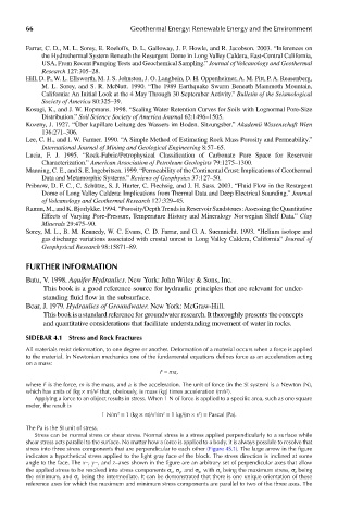
Stress can be normal stress or shear stress. Normal stress is a stress applied perpendicularly to a surface while
shear stress acts parallel to the surface. No matter how a force is applied to a body, it is always possible to resolve that
stress into three stress components that are perpendicular to each other (Figure 4S.1). The large arrow in the figure
indicates a hypothetical stress applied to the light gray face of the block. The stress direction is inclined at some
angle to the face. The x−, y−, and z–axes shown in the figure are an arbitrary set of perpendicular axes that allow
the applied stress to be resolved into stress components σ x , σ y , and σ z , with σ x being the maximum stress, σ z being
the minimum, and σ y being the intermediate. It can be demonstrated that there is one unique orientation of these
reference axes for which the maximum and minimum stress components are parallel to two of the three axes. The