
Page 231 - HVAC Pump Handbook
P. 231
Rishel_CH08.qxd 21/4/06 6:16 PM Page 228
The Use of Water in HVAC Systems
228 The HVAC World
8.3.3 Contemporary two-way valve connection
The ability to evaluate more accurately the pressure drops that could
occur across control valves has resulted in the selection of valves bet-
ter fitted to a specific application. This has culminated in use of the
two-way valve directly connected to its coil and the supply and return
headers (see Fig. 8.5c). With proper calculation of maximum possible
pressure drop across the valve, the valve and its actuator can be sized
to operate under these pressures without damage or lifting of the
valve head off the valve seat.
8.3.4 Energy evaluations for three different
coil connections
Following are energy analyses using these three coil and control-valve
connections. This energy audit should demonstrate the need to elimi-
nate three-way valves and coil circulators on most variable-volume
systems. Circulators in coil bypasses do have specific uses on existing
systems, and these will be demonstrated in this chapter.
It is difficult to locate the right place in this book for the following
energy discussion. This is so important that it must be addressed
before specific installations are reviewed. Chapter 9 will develop the
primary/secondary pumping systems that were used with the older
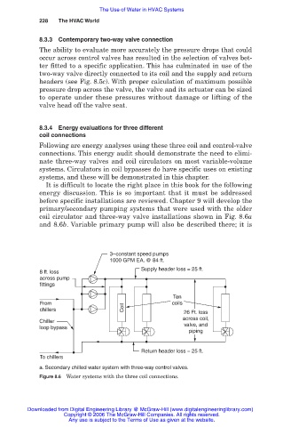
coil circulator and three-way valve installations shown in Fig. 8.6a
and 8.6b. Variable primary pump will also be described there; it is
3–constant speed pumps
1000 GPM EA. @ 84 ft.
Supply header loss = 25 ft.
8 ft. loss
across pump
fittings
Ten
From coils
chillers Coil 26 Ft. loss
across coil,
Chiller
loop bypass valve, and
piping
Return header loss = 25 ft.
To chillers
a. Secondary chilled water system with three-way control valves.
Figure 8.6 Water systems with the three coil connections.
Downloaded from Digital Engineering Library @ McGraw-Hill (www.digitalengineeringlibrary.com)
Copyright © 2006 The McGraw-Hill Companies. All rights reserved.
Any use is subject to the Terms of Use as given at the website.