
Page 235 - HVAC Pump Handbook
P. 235
Rishel_CH08.qxd 21/4/06 6:16 PM Page 232
The Use of Water in HVAC Systems
232 The HVAC World
Adding Tables 8.3 and 8.4 together into Table 8.5 gives the total
energy effect that the three coil and valve arrangements will have on
a chilled water system. It is obvious from this table that by far the
two-way valve without a circulator is the most efficient arrangement
of cooling coils and their control valves.
Tables 8.3 through 8.5 demonstrate the great variation of energy
caused by the various coil and control-valve arrangements. It must be
remembered that these tables were computed using specific chiller
and boiler efficiencies. A comparison of actual coil and valve arrange-
ments requires the determination of these efficiencies.
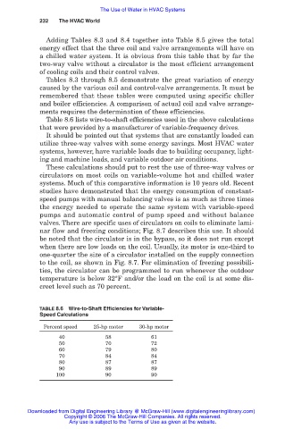
Table 8.6 lists wire-to-shaft efficiencies used in the above calculations
that were provided by a manufacturer of variable-frequency drives.
It should be pointed out that systems that are constantly loaded can
utilize three-way valves with some energy savings. Most HVAC water
systems, however, have variable loads due to building occupancy, light-
ing and machine loads, and variable outdoor air conditions.
These calculations should put to rest the use of three-way valves or
circulators on most coils on variable-volume hot and chilled water
systems. Much of this comparative information is 10 years old. Recent
studies have demonstrated that the energy consumption of constant-
speed pumps with manual balancing valves is as much as three times
the energy needed to operate the same system with variable-speed
pumps and automatic control of pump speed and without balance
valves. There are specific uses of circulators on coils to eliminate lami-
nar flow and freezing conditions; Fig. 8.7 describes this use. It should
be noted that the circulator is in the bypass, so it does not run except
when there are low loads on the coil. Usually, its motor is one-third to
one-quarter the size of a circulator installed on the supply connection
to the coil, as shown in Fig. 8.7. For elimination of freezing possibili-
ties, the circulator can be programmed to run whenever the outdoor
temperature is below 32°F and/or the load on the coil is at some dis-
creet level such as 70 percent.
TABLE 8.6 Wire-to-Shaft Efficiencies for Variable-
Speed Calculations
Percent speed 25-hp motor 30-hp motor
40 58 61
50 70 72
60 79 80
70 84 84
80 87 87
90 89 89
100 90 90
Downloaded from Digital Engineering Library @ McGraw-Hill (www.digitalengineeringlibrary.com)
Copyright © 2006 The McGraw-Hill Companies. All rights reserved.
Any use is subject to the Terms of Use as given at the website.