
Page 254 - HVAC Pump Handbook
P. 254
Rishel_09.qxd 20/4/06 6:34 PM Page 251
Configuring an HVAC Water System
Configuring an HVAC Water System 251
As described in Part 1 on pipe design, the formulas for pipe friction
reveal that pipe friction varies as parabolic curves with exponents
from 1.85 to 2.00. The total system head curve is achieved by adding
the static or constant friction head to the system friction head; the fol-
lowing equation can be used for calculation of the uniform system
head curve for a hot or chilled water system:
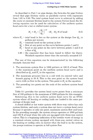
2
Q
a
H H 1.90 (H H ) ft of head (9.3)
a Q 1 2
1
where H total head in feet on the system at the design flow Q ,in
1 1
gallons per minute
H constant head on the system in feet
2
Q flow at any point on the curve between points 1 and 2
a
H head at any point on the curve between points 1 and 2 at
a
a flow of Q
a
1.90 the exponent that has been found to follow the Darcy-
Weisbach equation closer than the normally accepted 2.0
The use of this equation can be demonstrated by the following
example. Assume that
1. The maximum system flow is 1000 gal/min at 100 ft of head. This
is the maximum point on the uniform system head curve and is
identified as Q and H in the equation.
1 1
2. The maximum pressure loss in a coil with its control valve and
branch piping is 20 ft. This is the zero point on the system head
curve with no flow in the system. This point is H in the equation.
2
3. The preceding two points set the ends of the uniform system head
curve.
Table 9.1 provides the system head curve points from a minimum
flow of 100 gal/min to the maximum of 1000 gal/min for this example.
Reiterating, this is the uniform system head curve for an HVAC
system where all heating or cooling loads are loaded to the same per-
centage of design load.
A closed chilled or hot water system with three-way valves has only
system friction, and such a system does not have a system head curve
because it operates at only one point, maximum system flow and head.
In the preceding example, the system always operates at 1000 gal/min
and 100 ft of head when the coils are equipped with three-way control
valves. This is a beginning indication of the terrible waste of energy in
a constant-volume system equipped with three-way control valves on
the heating or cooling coils; no matter what the load is on the system,
the pumps continue to operate at full system flow.
Downloaded from Digital Engineering Library @ McGraw-Hill (www.digitalengineeringlibrary.com)
Copyright © 2006 The McGraw-Hill Companies. All rights reserved.
Any use is subject to the Terms of Use as given at the website.