Page 89 - Hacking Roomba
P. 89

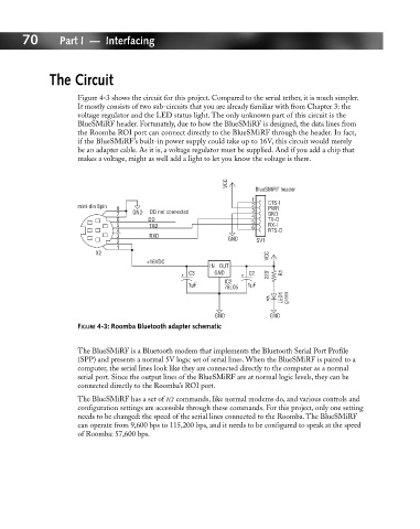
70       Part I — Interfacing


                     The Circuit


                             Figure 4-3 shows the circuit for this project. Compared to the serial tether, it is much simpler.
                             It mostly consists of two sub-circuits that you are already familiar with from Chapter 3: the
                             voltage regulator and the LED status light. The only unknown part of this circuit is the
                             BlueSMiRF header. Fortunately, due to how the BlueSMiRF is designed, the data lines from
                             the Roomba ROI port can connect directly to the BlueSMiRF through the header. In fact,
                             if the BlueSMiRF’s built-in power supply could take up to 16V, this circuit would merely
                             be an adapter cable. As it is, a voltage regulator must be supplied. And if you add a chip that
                             makes a voltage, might as well add a light to let you know the voltage is there.

                                                                  VCC
                                                                          BlueSMiRF header
                                                                         1   CTS-I
                             mini-din 8pin  8                            2   PWR
                                      7    GND  DD not connected         3   GND
                                                                         4
                                      6       DD                         5   TX-O
                                      5        TXD                       6   RX-I
                                      4                                      RTS-O
                                      3        RXD                 GND
                                      2                                   SV1
                                      1
                                 X2                                          VCC
                                              +16VDC
                                                              IN OUT
                                                         C3    GND      C2   220'   R1
                                                                  IC2
                                                         1µF      78L05   1µF
                                                                                LED1   green
                                                               GND           GND
                             FIGURE 4-3: Roomba Bluetooth adapter schematic


                             The BlueSMiRF is a Bluetooth modem that implements the Bluetooth Serial Port Profile
                             (SPP) and presents a normal 5V logic set of serial lines. When the BlueSMiRF is paired to a
                             computer, the serial lines look like they are connected directly to the computer as a normal
                             serial port. Since the output lines of the BlueSMiRF are at normal logic levels, they can be
                             connected directly to the Roomba’s ROI port.

                             The BlueSMiRF has a set of AT commands, like normal modems do, and various controls and
                             configuration settings are accessible through these commands. For this project, only one setting
                             needs to be changed: the speed of the serial lines connected to the Roomba. The BlueSMiRF
                             can operate from 9,600 bps to 115,200 bps, and it needs to be configured to speak at the speed
                             of Roomba: 57,600 bps.
   84   85   86   87   88   89   90   91   92   93   94