
Page 91 - Hacking Roomba
P. 91
72 Part I — Interfacing
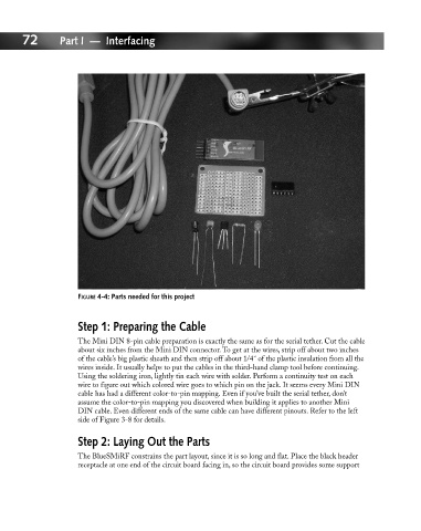
FIGURE 4-4: Parts needed for this project
Step 1: Preparing the Cable
The Mini DIN 8-pin cable preparation is exactly the same as for the serial tether. Cut the cable
about six inches from the Mini DIN connector. To get at the wires, strip off about two inches
of the cable’s big plastic sheath and then strip off about 1/4˝ of the plastic insulation from all the
wires inside. It usually helps to put the cables in the third-hand clamp tool before continuing.
Using the soldering iron, lightly tin each wire with solder. Perform a continuity test on each
wire to figure out which colored wire goes to which pin on the jack. It seems every Mini DIN
cable has had a different color-to-pin mapping. Even if you’ve built the serial tether, don’t
assume the color-to-pin mapping you discovered when building it applies to another Mini
DIN cable. Even different ends of the same cable can have different pinouts. Refer to the left
side of Figure 3-8 for details.
Step 2: Laying Out the Parts
The BlueSMiRF constrains the part layout, since it is so long and flat. Place the black header
receptacle at one end of the circuit board facing in, so the circuit board provides some support