
Page 94 - Hacking Roomba
P. 94
Chapter 4 — Building a Roomba Bluetooth Interface 75
loop some stray insulated wire around the cable and into the circuit board holes and twist tight.
Also, add a bit of hot glue to the header receptacle to secure it to the board so plugging and
unplugging the BlueSMiRF doesn’t stress the solder joints.
With the cables and header receptacle secured down with hot glue, solder the wires and recep-
tacle pins down. In general you want to secure connectors and wires before soldering them so
any flex of those parts doesn’t affect the solder joints.
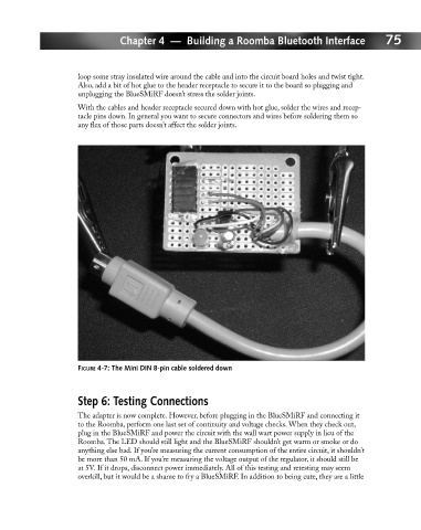
FIGURE 4-7: The Mini DIN 8-pin cable soldered down
Step 6: Testing Connections
The adapter is now complete. However, before plugging in the BlueSMiRF and connecting it
to the Roomba, perform one last set of continuity and voltage checks. When they check out,
plug in the BlueSMiRF and power the circuit with the wall wart power supply in lieu of the
Roomba. The LED should still light and the BlueSMiRF shouldn’t get warm or smoke or do
anything else bad. If you’re measuring the current consumption of the entire circuit, it shouldn’t
be more than 50 mA. If you’re measuring the voltage output of the regulator, it should still be
at 5V. If it drops, disconnect power immediately. All of this testing and retesting may seem
overkill, but it would be a shame to fry a BlueSMiRF. In addition to being cute, they are a little