
Page 92 - Hacking Roomba
P. 92
Chapter 4 — Building a Roomba Bluetooth Interface 73
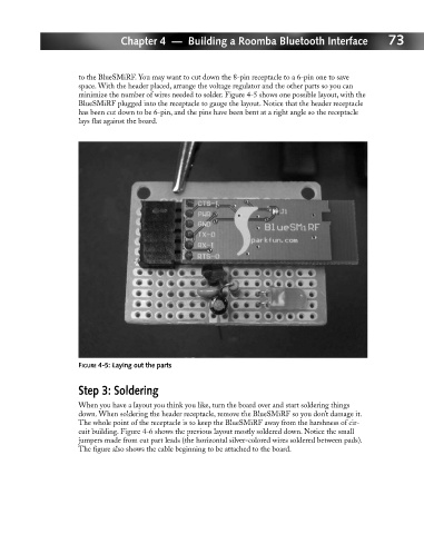
to the BlueSMiRF. You may want to cut down the 8-pin receptacle to a 6-pin one to save
space. With the header placed, arrange the voltage regulator and the other parts so you can
minimize the number of wires needed to solder. Figure 4-5 shows one possible layout, with the
BlueSMiRF plugged into the receptacle to gauge the layout. Notice that the header receptacle
has been cut down to be 6-pin, and the pins have been bent at a right angle so the receptacle
lays flat against the board.
FIGURE 4-5: Laying out the parts
Step 3: Soldering
When you have a layout you think you like, turn the board over and start soldering things
down. When soldering the header receptacle, remove the BlueSMiRF so you don’t damage it.
The whole point of the receptacle is to keep the BlueSMiRF away from the harshness of cir-
cuit building. Figure 4-6 shows the previous layout mostly soldered down. Notice the small
jumpers made from cut part leads (the horizontal silver-colored wires soldered between pads).
The figure also shows the cable beginning to be attached to the board.