
Page 93 - Hacking Roomba
P. 93
74 Part I — Interfacing
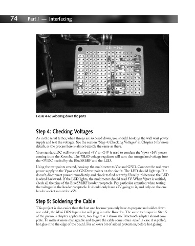
FIGURE 4-6: Soldering down the parts
Step 4: Checking Voltages
As in the serial tether, when things are soldered down, you should hook up the wall wart power
supply and test the voltages. See the section “Step 4: Checking Voltages” in Chapter 3 for more
details, as the process here is almost exactly the same as there.
Your standard DC wall wart of around +9V to +24V is used to emulate the Vpwr +16V power
coming from the Roomba. The 78L05 voltage regulator will turn that unregulated voltage into
the +5VDC needed by the BlueSMiRF and the LED.
Using the test points created, hook up the multimeter to Vcc and GND. Connect the wall wart
power supply to the Vpwr and GND test points on the circuit. The LED should light up. If it
doesn’t, disconnect power immediately and check to find out why. Usually it’s because the LED
is wired backward. If the LED lights, the multimeter should read 5V. When Vpwr is verified,
check all the pins of the BlueSMiRF header receptacle. Pay particular attention when testing
the voltages in the header receptacle. It should only have +5V going to it, and only on the one
header socket meant for +5V.
Step 5: Soldering the Cable
This project is also easier than the last one because you only have to prepare and solder down
one cable, the Mini DIN 8-pin that will plug into the Roomba. The same technique in Step 5
of the previous chapter applies here, too. Figure 4-7 shows the Bluetooth adapter almost com-
plete. To make it more manageable and to give the cable some strain-relief in case it is pulled,
hot glue it to the edge of the board. For an extra bit of added protection, before hot gluing,