
Page 113 - Handbook Of Multiphase Flow Assurance
P. 113
Hydrate of natural gas 109
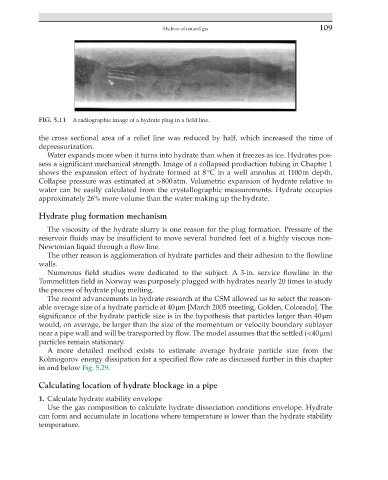
FIG. 5.11 A radiographic image of a hydrate plug in a field line.
the cross sectional area of a relief line was reduced by half, which increased the time of
depressurization.
Water expands more when it turns into hydrate than when it freezes as ice. Hydrates pos-
sess a significant mechanical strength. Image of a collapsed production tubing in Chapter 1
shows the expansion effect of hydrate formed at 8 °C in a well annulus at 1100 m depth.
Collapse pressure was estimated at >800 atm. Volumetric expansion of hydrate relative to
water can be easily calculated from the crystallographic measurements. Hydrate occupies
approximately 26% more volume than the water making up the hydrate.
Hydrate plug formation mechanism
The viscosity of the hydrate slurry is one reason for the plug formation. Pressure of the
reservoir fluids may be insufficient to move several hundred feet of a highly viscous non-
Newtonian liquid through a flow line.
The other reason is agglomeration of hydrate particles and their adhesion to the flowline
walls.
Numerous field studies were dedicated to the subject. A 3-in. service flowline in the
Tommelitten field in Norway was purposely plugged with hydrates nearly 20 times to study
the process of hydrate plug melting.
The recent advancements in hydrate research at the CSM allowed us to select the reason-
able average size of a hydrate particle at 40 μm [March 2005 meeting, Golden, Colorado]. The
significance of the hydrate particle size is in the hypothesis that particles larger than 40 μm
would, on average, be larger than the size of the momentum or velocity boundary sublayer
near a pipe wall and will be transported by flow. The model assumes that the settled (<40 μm)
particles remain stationary.
A more detailed method exists to estimate average hydrate particle size from the
Kolmogorov energy dissipation for a specified flow rate as discussed further in this chapter
in and below Fig. 5.29.
Calculating location of hydrate blockage in a pipe
1. Calculate hydrate stability envelope
Use the gas composition to calculate hydrate dissociation conditions envelope. Hydrate
can form and accumulate in locations where temperature is lower than the hydrate stability
temperature.