
Page 49 - Handbook Of Multiphase Flow Assurance
P. 49
44 3. PVT and rheology investigation
Pressure
Reservoir
Undersaturated Early Life
Liquid Dense Phase
Wellhead
Early Life
Reservoir
Late Life
Vapor
Vapor +
Saturated Liquid
Wellhead
Separator Separator Late Life
Late Life Early Life Temperature
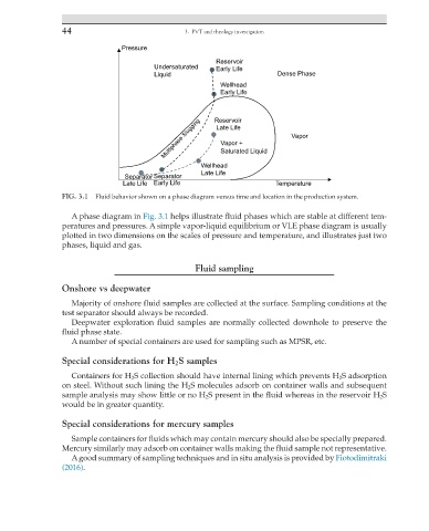
FIG. 3.1 Fluid behavior shown on a phase diagram versus time and location in the production system.
A phase diagram in Fig. 3.1 helps illustrate fluid phases which are stable at different tem-
peratures and pressures. A simple vapor-liquid equilibrium or VLE phase diagram is usually
plotted in two dimensions on the scales of pressure and temperature, and illustrates just two
phases, liquid and gas.
Fluid sampling
Onshore vs deepwater
Majority of onshore fluid samples are collected at the surface. Sampling conditions at the
test separator should always be recorded.
Deepwater exploration fluid samples are normally collected downhole to preserve the
fluid phase state.
A number of special containers are used for sampling such as MPSR, etc.
Special considerations for H 2 S samples
Containers for H 2 S collection should have internal lining which prevents H 2 S adsorption
on steel. Without such lining the H 2 S molecules adsorb on container walls and subsequent
sample analysis may show little or no H 2 S present in the fluid whereas in the reservoir H 2 S
would be in greater quantity.
Special considerations for mercury samples
Sample containers for fluids which may contain mercury should also be specially prepared.
Mercury similarly may adsorb on container walls making the fluid sample not representative.
A good summary of sampling techniques and in situ analysis is provided by Fiotodimitraki
(2016).