
Page 143 - Handbook of Battery Materials
P. 143
3.3 Layer Structures 111
MnO 6
octahedra
H 2 O
Foreign
cations
B2
B1
(a)
MnO 6
octahedra
H 2 O
Foreign
cations
(b)
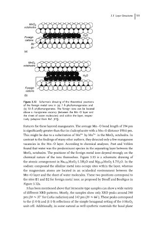
Figure 3.12 Schematic drawing of the theoretical positions
of the foreign metal ions in (a) 7 ˚ A phyllomanganates and
(b) 10 ˚ A phyllomanganates. The foreign ions can be located
above a manganese vacancy (between the Mn–O layer and
the sheet of water molecules) and within the layer, respec-
tively (adapted from Ref. [41]).
features for these layered manganates. The average Mn–O bond length of 194 pm
is significantly greater than that in chalcophanite with a Mn–O distance 190.6 pm.
This might be due to a substitution of Mn 4+ by Mn 3+ in the MnO 6 octahedra. In
contrast to the findings of many other authors, they detected only a few manganese
vacancies in the Mn–O layer. According to chemical analyses, Post and Veblen
found that water was the predominant species in the separating layer between the
MnO 6 octahedra. The positions of the foreign metal ions depend strongly on the
chemical nature of the ions themselves. Figure 3.13 is a schematic drawing of
the atomic arrangement in Na 0.58 MnO 2 ·1.5H 2 O and Mg 0.29 MnO 2 ·1.7H 2 O. In the
sodium compound the alkaline metal ions occupy sites within the layer, whereas
the magnesium atoms are located in an octahedral environment between the
Mn–O layer and the sheet of water molecules. These two positions correspond to
the sites B1 and B2 for foreign metal ions, as proposed by Stouff and Boul` egue in
Figure 3.12a.
It has been mentioned above that birnessite-type samples can show a wide variety
of different XRD patterns. Mostly, the samples show only XRD peaks around 240
◦
pm (2θ ≈ 37 for CuKα radiation) and 142 pm (2θ ≈ 66 ). These peaks correspond
◦
to the (1 0 0) and (1 1 0) reflections of the simple hexagonal setting of the δ-MnO 2
unit cell. Additionally, in some natural as well synthetic materials the basal plane