
Page 78 - Handbook of Battery Materials
P. 78
44 2 Practical Batteries
Mn 4+ O = Mn 4+ O =
e - = = +
O Mn 4+ O Mn 4+ Li
Mn 3+ O = Mn 4+ O = Li +
O = 3+ O = 3+
Mn Mn Li Nonaqueous
+
Mn 4+ OLi - Mn 4+ OLi - electrolyte
Li +
O = Mn 4+ O = Mn 4+
X Y
Figure 2.26 Schematic presentation of the solid phase
during the discharge of MnO 2 . The arrows show direc-
tions of movement of the electrons and lithium ions:
→, lithium–ion movement;→, electron movement; X,
MnO 2 –electronic conductor interface; and Y, MnO 2 –solution
interface.
Residual capacity ratio (%) 90
100
80
70
Cell type : CR2025
Storage condition 60°C : 11 months
60
Load : 5.6kΩ
Temperature : 20°C
200 300 400 500
MnO 2 heat treatment temperature (°C)
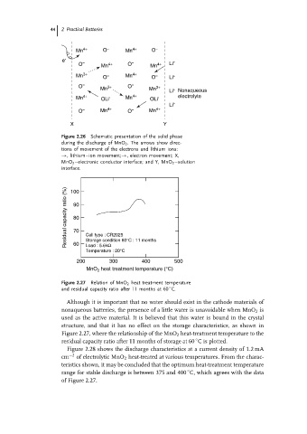
Figure 2.27 Relation of MnO 2 heat treatment temperature
◦
and residual capacity ratio after 11 months at 60 C.
Although it is important that no water should exist in the cathode materials of
nonaqueous batteries, the presence of a little water is unavoidable when MnO 2 is
used as the active material. It is believed that this water is bound in the crystal
structure, and that it has no effect on the storage characteristics, as shown in
Figure 2.27, where the relationship of the MnO 2 heat-treatment temperature to the
◦
residual capacity ratio after 11 months of storage at 60 C is plotted.
Figure 2.28 shows the discharge characteristics at a current density of 1.2 mA
cm −2 of electrolytic MnO 2 heat-treated at various temperatures. From the charac-
teristics shown, it may be concluded that the optimum heat-treatment temperature
◦
range for stable discharge is between 375 and 400 C, which agrees with the data
of Figure 2.27.