
Page 177 - Handbook of Civil Engineering Calculations, Second Edition
P. 177
1.160 STRUCTURAL STEEL ENGINEERING AND DESIGN
( c P n 768 kips for this case is also tabulated on p. 4-73 of the AISC LRFD Manual.)
The 768-kip design strength is considerably more than the 238-kip (1640 Mpa) design
strength of a noncomposite W8 40 column under the same conditions.
Related Calculations. This procedure is the work of Abraham J. Rokach, MSCE, As-
sociate Director of Education, American Institute of Steel Construction. SI values were
prepared by the handbook editor.
ANALYZING A CONCRETE SLAB
FOR COMPOSITE ACTION
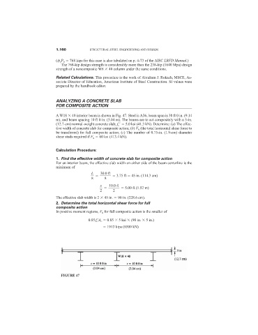
A W18 40 interior beam is shown in Fig. 47. Steel is A36, beam span is 30 ft 0 in. (9.14
m), and beam spacing 10 ft 0 in. (3.04 m). The beams are to act compositely with a 5-in.
(12.7-cm) normal-weight concrete slab; f c
5.0 ksi (41.3 kN). Determine: (a) The effec-
tive width of concrete slab for composite action; (b) V h (the total horizontal shear force to
be transferred) for full composite action; (c) The number of 0.75-in. (1.9-cm) diameter
shear studs required if F u 60 ksi (413.4 kN).
Calculation Procedure:
1. Find the effective width of concrete slab for composite action
For an interior beam, the effective slab width on either side of the beam centerline is the
minimum of
L 30.0 ft
3.75 ft 45 in. (114.3 cm)
8 8
s 10.0 ft
5.00 ft (1.52 m)
2 2
The effective slab width is 2 45 in. 90 in. (228.6 cm).
2. Determine the total horizontal shear force for full
composite action
In positive moment regions, V h for full composite action is the smaller of
0.85f c
A c 0.85 5 ksi (90 in. 5 in.)
1913 kips (8509 kN)
FIGURE 47