
Page 179 - Handbook of Civil Engineering Calculations, Second Edition
P. 179
1.162 STRUCTURAL STEEL ENGINEERING AND DESIGN
DETERMINING THE DESIGN SHEAR
STRENGTH OF A BEAM WEB
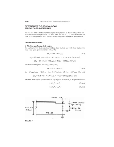
The end of a W12 86 beam (A36 steel) has been prepared as shown in Fig. 49 for con-
15
nection to a supporting member. The three holes are /16 in. (2.38 cm) in diameter for
7 /8-in. (2.22-cm)-diameter bolts. Determine the design shear strength of the beam web.
Calculation Procedure:
1. Find the applicable limit states
The applicable limit states are shear yielding, shear fracture, and block shear rupture. For
shear yielding [of gross section (1) in Fig. 49 ]
(J5-3)
R n 0.90 0.6A vg F y
2
A vg (d-cope)t (12.53 in. – 2 in.) 0.515 in. 5.42 sq.in. (34.96 cm )
R n 0.9 0.6 5.42 sq.in. 36 ksi 105 kips (467 kN)
For shear fracture [of net section (1) in Fig. 11-9]
(J4-1)
R n 0.75 0.6A ns F u
2
A ns (d-cope-3d h )t (12.53 in. – 2 in. – 3 /16 in.) 0.515 in. 3.97 sq.in. (25.6 cm )
15
R n 0.75 0.6 3.97 sq.in. 58 ksi 104 kips (462.6 kN)
For block shear rupture [of section (2) in Fig. 49] 0.75 and R n the greater value of
(C-J4-1)
0.6A vg F y + A n F u
(C-J4-2)
0.6A ns F u + A g F y
FIGURE 49