
Page 301 - Handbook of Civil Engineering Calculations, Second Edition
P. 301
2.86 REINFORCED AND PRESTRESSED CONCRETE ENGINEERING AND DESIGN
5. Consider that a concordant trajectory has been plotted; express the
eccentricity at section B relative to that at section 2
Thus, e b /e 2 0.1250/ 0.0700 1.786; therefore, e b 1.786e 2 .
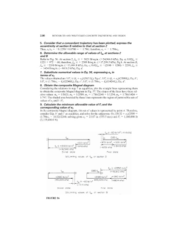
6. Determine the allowable range of values of f bp at sections 2
and B
Refer to Fig. 56. At section 2, f bp 3621 lb/sq.in. ( 24,966.8 kPa), Eq. a; 0.85f bp
1221 972 60; therefore, f bp 2509 lb/sq.in. ( 17,299.5 kPa), Eq b. At section B,
f bp 2240 lb/sq.in. ( 15,444.8 kPa), Eq. c; 0.85f bp (2180 1280) 2250; f bp
1424 lb/sq.in. ( 9818.5 kPa), Eq. d.
7. Substitute numerical values in Eq. 56, expressing e b in
terms of e 2
The values obtained are 1/F i (k t e 2 )/(3621S b ), Eq a
; 1/F i (k t e 2 )/(2509S b ), Eq. b
;
1/F t (1.786e 2 k t )/(2240S b ), Eq. c
; 1/F i (1.786e 2 k t )/(1424S b ), Eq. d
.
8. Obtain the composite Magnel diagram
Considering the relations in step 7 as equalities, plot the straight lines representing them
to obtain the composite Magnel diagram in Fig. 57. The slopes of the lines have these rel-
ative values: m a 1/3621; m b 1/2509; m c 1.786/2240 1/1254; m d 1.786/1424
1/797. The shaded area bounded by these lines represents the region of permissible sets of
values of e 2 and 1 /F i .
9. Calculate the minimum allowable value of F i and the
corresponding value of e 2
In the composite Magnel diagram, this set of values is represented by point A. Therefore,
consider Eqs. b
and c
as equalities, and solve for the unknowns. Or, (10.32 e 2 )/2509
(1.786e 2 10.32)/2240; solving gives e 2 21.87 in. (555.5 mm) and F i 1,160,000 lb
(5,159,680.0 N).
FIGURE 56