
Page 299 - Handbook of Civil Engineering Calculations, Second Edition
P. 299
2.84 REINFORCED AND PRESTRESSED CONCRETE ENGINEERING AND DESIGN
moment, expressing each moment in terms of the distance from a given section to the adja-
cent exterior support. Second, apply these equations to identify the sections at which the ini-
tial and final stresses are critical. Third, design the prestressing system to restrict the critical
stresses to their allowable range. Whereas the exact method is not laborious when applied to
a prismatic beam carrying uniform loads, this procedure adopts the conventional, simplified
method for illustrative purposes. This consists of dividing each span into a suitable number of
intervals and analyzing the stresses at each boundary section.
For simplicity, set the eccentricity at the ends equal to zero. The trajectory will be
symmetric about the interior support, and the vertical component w of the force exerted
by the tendons on the concrete in a unit longitudinal distance will be uniform across the
entire length of member. Therefore, the prestress-moment diagram has the same form as
the bending-moment diagram of a nonprestressed prismatic beam continuous over two
equal spans and subjected to a uniform load across its entire length. It follows as a corol-
lary that the prestress moments at the boundary sections previously referred to have spe-
cific relative values although their absolute values are functions of the prestressing force
and its trajectory.
The following steps constitute a methodical procedure: Evaluate the relative prestress
moments, and select a trajectory having ordinates directly proportional to these moments.
The trajectory thus fashioned is concordant. Compute the prestressing force required to
restrict the stresses to the allowable range. Then transform the concordant trajectory lin-
early to secure one that lies entirely within the confines of the section. Although the num-
ber of satisfactory concordant trajectories is infinite, the one to be selected is that which
requires the minimum prestressing force. Therefore, the selection of the trajectory and the
calculation of F i are blended into one operation.
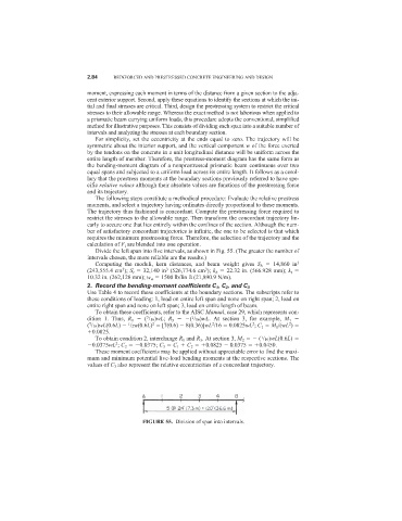
Divide the left span into five intervals, as shown in Fig. 55. (The greater the number of
intervals chosen, the more reliable are the results.)
Computing the moduli, kern distances, and beam weight gives S b 14,860 in 3
3
3
(243,555.4 cm ); S t 32,140 in (526,774.6 cm ); k b 22.32 in. (566.928 mm); k t
3
10.32 in. (262,128 mm); w w 1500 lb/lin ft (21,890.9 N/m).
2. Record the bending-moment coefficients C 1 , C 2 , and C 3
Use Table 4 to record these coefficients at the boundary sections. The subscripts refer to
these conditions of loading: 1, load on entire left span and none on right span; 2, load on
entire right span and none on left span; 3, load on entire length of beam.
To obtain these coefficients, refer to the AISC Manual, case 29, which represents con-
dition 1. Thus, R 1 ( /16)wL; R 3 ( /16)wL. At section 3, for example, M 1
1
7
2
2
2
2
( /16)wL(0.6L) /2w(0.6L) [7(0.6) 8(0.36)]wL /16 0.0825wL ; C 1 M 1 /(wL )
7
1
0.0825.
To obtain condition 2, interchange R 1 and R 3 . At section 3, M 2 ( /16)wL(0.6L)
1
2
0.0375wL ; C 2 0.0375; C 3 C 1 C 2 0.0825 0.0375 0.0450.
These moment coefficients may be applied without appreciable error to find the maxi-
mum and minimum potential live-load bending moments at the respective sections. The
values of C 3 also represent the relative eccentricities of a concordant trajectory.
FIGURE 55. Division of span into intervals.