
Page 295 - Handbook of Civil Engineering Calculations, Second Edition
P. 295
2.80 REINFORCED AND PRESTRESSED CONCRETE ENGINEERING AND DESIGN
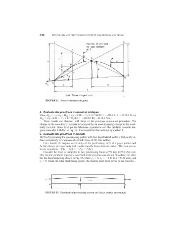
FIGURE 52. Prestress moment diagram.
4. Evaluate the prestress moment at midspan
1
Thus, M pd F i e d M kd F i ( 0.20 /2 0.776)/12 4704 ft·lb ( 6378.6 N·m);
1
M pe F i ( 0.24 /2 0.776)/12 5024 ft·lb ( 6812.5 N·m).
These results are identical with those in the previous calculation procedure. The
change in the eccentricity moment is balanced by an accompanying change in the conti-
nuity moment. Since three points determine a parabolic arc, the prestress moment dia-
gram coincides with that in Fig. 52. This constitutes the solution by method 1.
5. Evaluate the prestress moments
Do this by replacing the prestressing system with two hypothetical systems that jointly in-
duce eccentricity moments identical with those of the true system.
Let e denote the original eccentricity of the prestressing force at a given section and
e the change in eccentricity that results from the linear transformation. The final eccen-
tricity moment is F i (e e) (F i e F i e).
Consider the beam as subjected to two prestressing forces of 96 kips (427.0 kN) each.
One has the parabolic trajectory described in the previous calculation procedure; the other
has the linear trajectory shown in Fig. 53, where e a 0, e b 0.80 in. ( 20.32 mm), and
e c 0. Under the latter prestressing system, the tendons exert three forces on the concrete—
FIGURE 53. Hypothetical prestressing system and forces exerted on concrete.