
Page 293 - Handbook of Civil Engineering Calculations, Second Edition
P. 293
2.78 REINFORCED AND PRESTRESSED CONCRETE ENGINEERING AND DESIGN
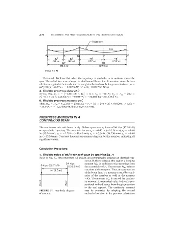
FIGURE 50
This result discloses that when the trajectory is parabolic, w is uniform across the
span. The radial forces are always directed toward the center of curvature, since the ten-
sile forces applied at their ends tend to straighten the tendons. In the present instance, w
2
(4F i /100 )( 62/12) 0.002067F i lb/lin ft ( 0.00678F i N/m).
4. Find the prestress shear at C
By Eq. 69a, m a [ 120/(100 12)] 0.1; V pa 0.1F i ; V pc V pa 20w
F i ( 0.1 20 0.002067) 0.0587F i 50,480 lb ( 224,535.0 N).
5. Find the prestress moment at C
Thus, M pc M pa V pa (240) 20w(120) F i 0.1 240 20 0.002067 120)
20.04F i 17,230,000 in.·lb (1,946,645.4 N·m).
PRESTRESS MOMENTS IN A
CONTINUOUS BEAM
The continuous prismatic beam in Fig. 50 has a prestressing force of 96 kips (427.0 kN)
on a parabolic trajectory. The eccentricities are e a 0.40 in. ( 10.16 mm); e d 0.60
in. (15.24 mm); e b 1.20 in. ( 30.48 mm); e e 0.64 in. (16.256 mm); e c 0.60
in. ( 15.24 mm). Construct the prestress-moment diagram for this member, indicating all
significant values.
Calculation Procedure:
2
1. Find the value of wL /4 for each span by applying Eq. 71
Refer to Fig. 52. Since members AB and BC are constrained to undergo an identical rota-
tion at B, there exists at this section a bending
moment M kb in addition to that resulting from
the eccentricity of F i . The moment M kb induces
reactions at the supports. Thus, at every section
of the beam there is a moment caused by conti-
nuity of the member as well as the moment
F i e. The moment M kb is termed the continu-
ity moment; its numerical value is directly pro-
portional to the distance from the given section
to the end support. The continuity moment
FIGURE 51. Free-body diagram may be evaluated by adopting the second
of concrete. method of solution in the previous calculation